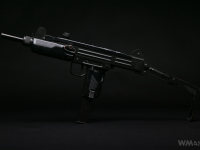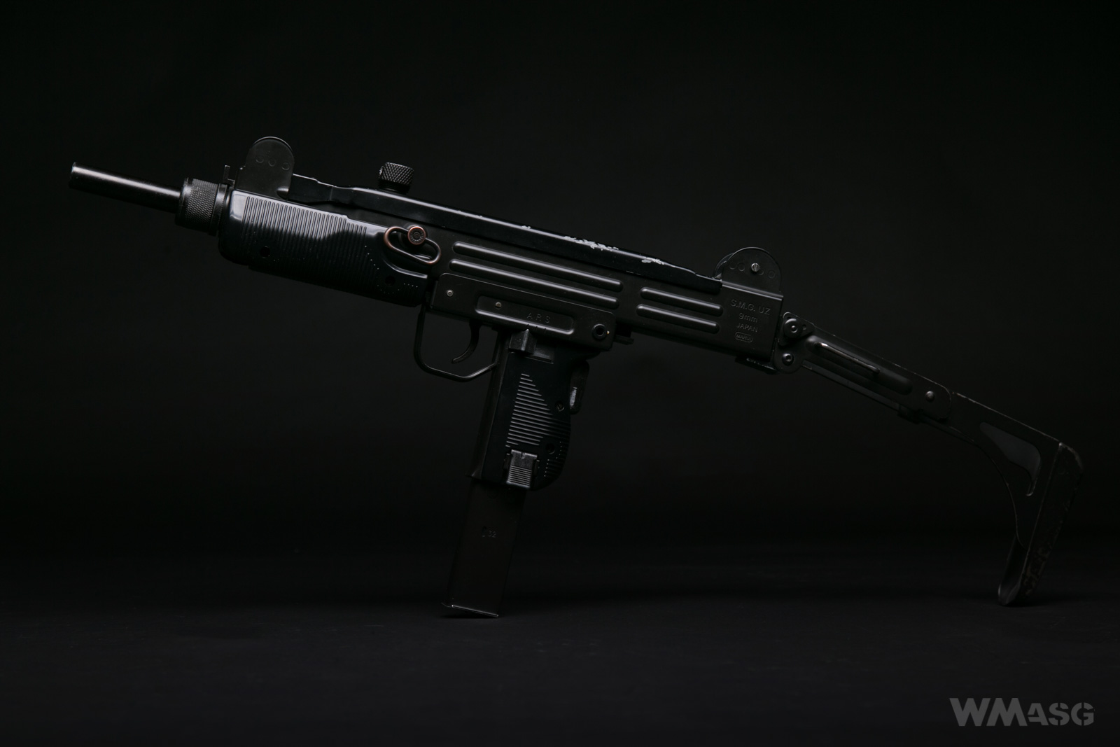

Interested? Lest get it on!
The gearbox in the UZI is a V5. Designed specifically for this replica. He did not appear anywhere else later in any replica. It is made entirely of ABS.
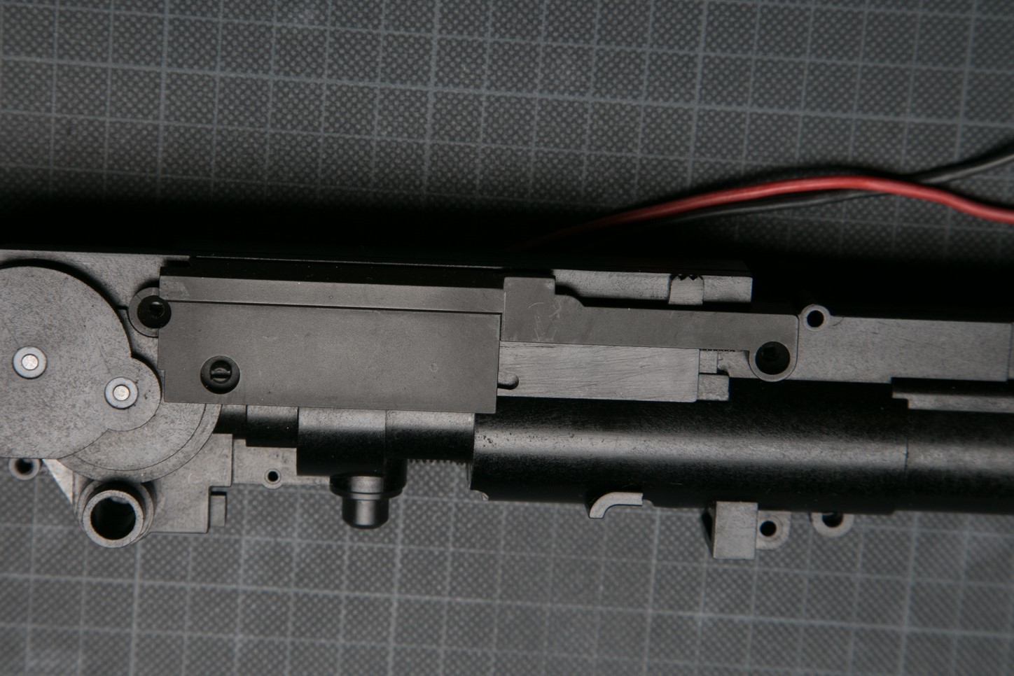
The whole mechanism is enclosed in a single housing. Including the HopUp chamber and the inner barrel. The picture lacks a motor that is held in its place with the parts of the receiver.
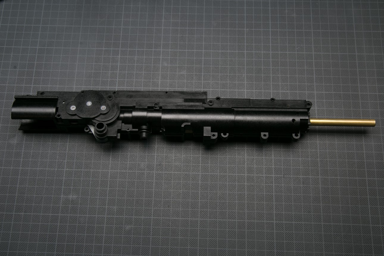
The trigger switch and the wires are placed completely outside on the left side. In the described unit they were replaced by the previous owner.
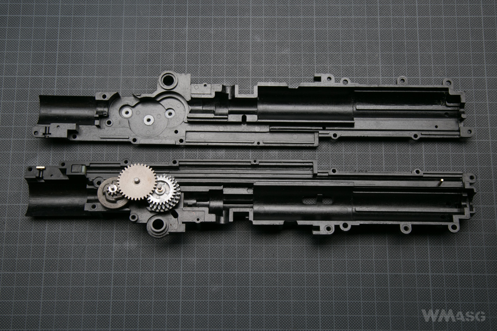
The frame itself. The typical Marui 6-millimeter Teflon bushings are clearly visible.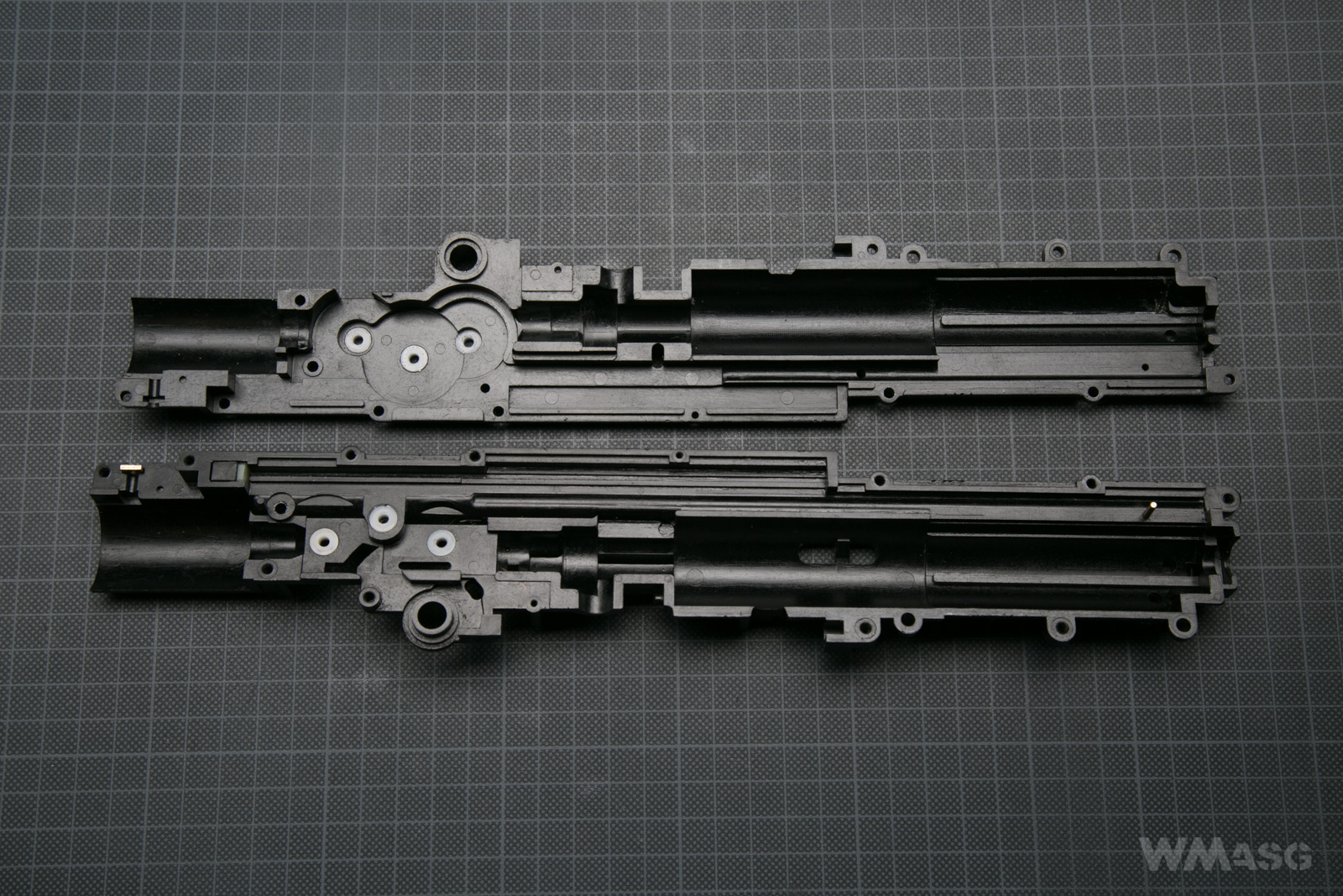
The front (of the barrel) is on the right side. In addition to the all-in-one design, the UZI's gearbox stands out with yet another absolutely unique feature. It has the entire pneumatic system reversed. That is, the spring is located on the side of the barrel exit, and the piston compresses the air in the cylinder in the direction of the shooter. The change of the air flow direction takes place in the HopUp chamber. To make it even more funny, the gears are placed on the opposite side of the mechanism than the cylinder and the piston. The movement of the sector gear wheel is transferred to the piston through a toothed rack and a special rod. I have not seen such a solution in any other gearbox. I will describe the method of its operation in a moment.
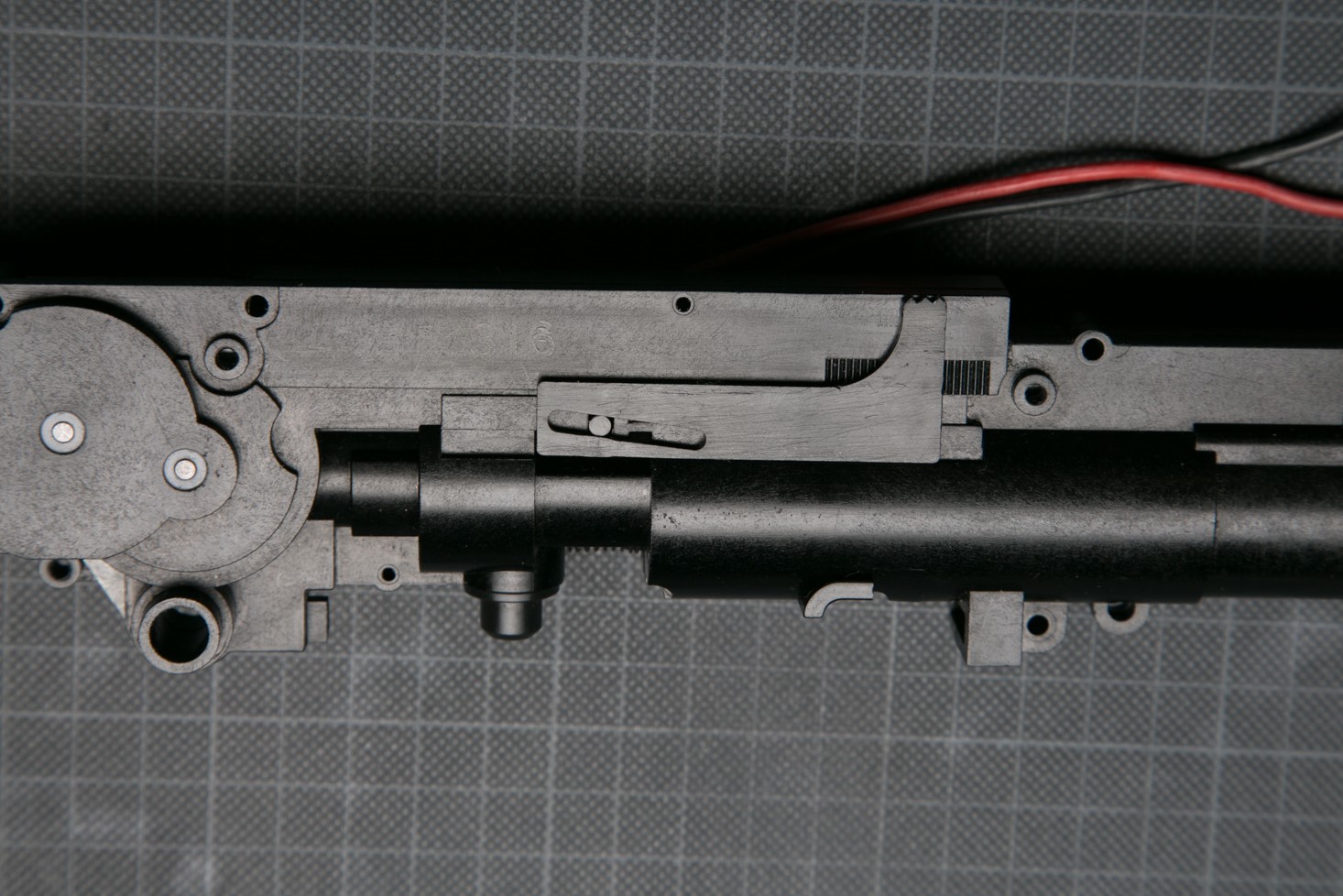
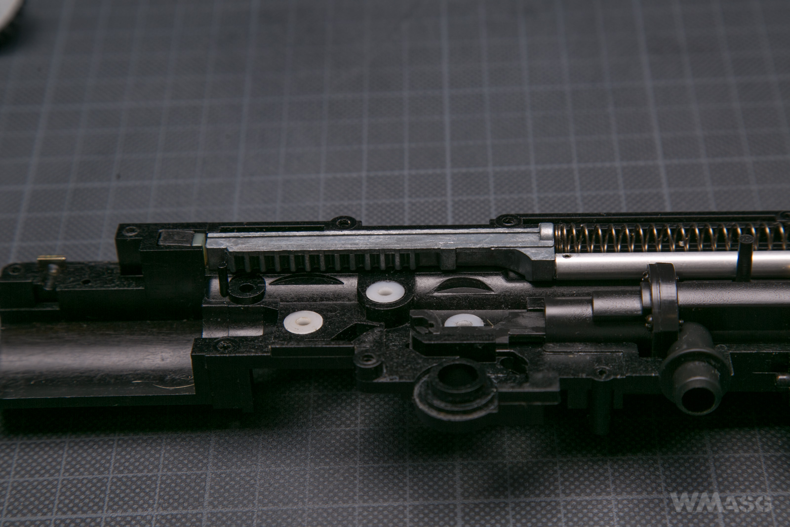
Meanwhile, the almost complete mechanism (only the motor is missing):
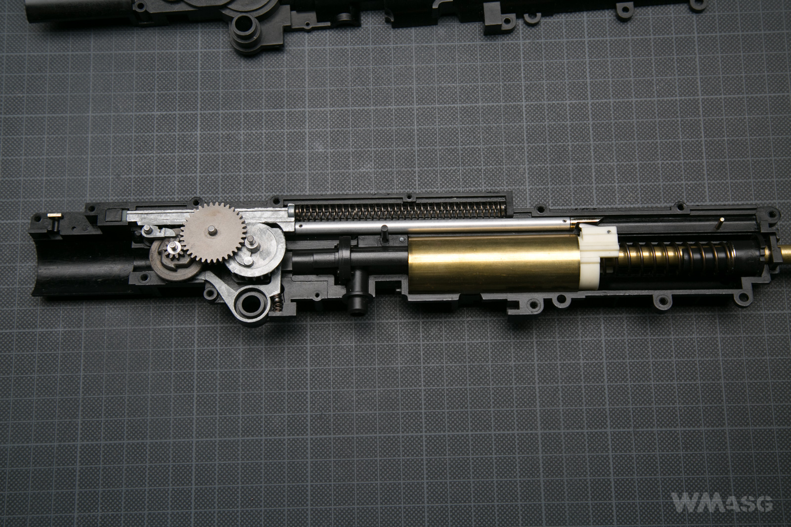
Once again, with captions:
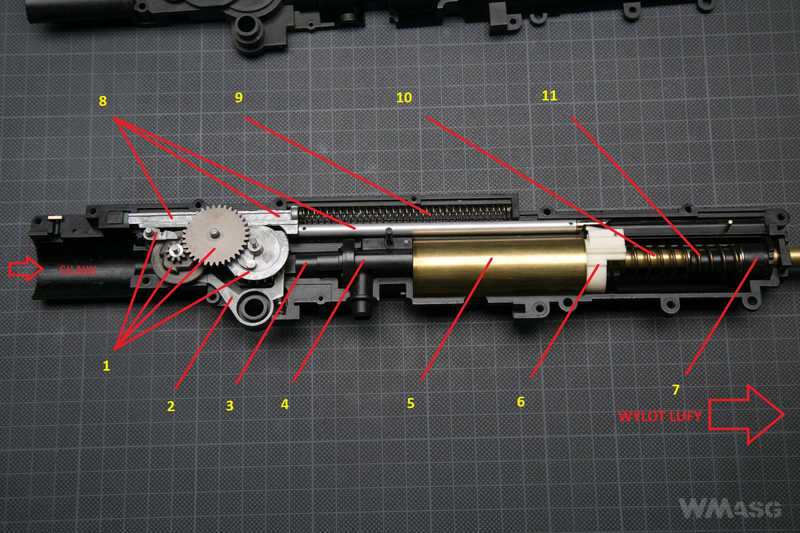
1. Gears with the anti-reversal latch. As a rule, they work like in any other gearbox, but they are unique (made only for the UZI) and they rotate in the opposite direction (the sector gear turns clockwise);
2. The cut-off lever (driven by sector gear, it disconnects the contact surfaces in the single fire mode);
3. The nozzle;
4. The HopUp chamber;
5. The cylinder;
6. The piston (the rest is invisible, hidden in the cylinder);
7. The spring guide;
8. The piston rod (its a long part therefore it has three indicating lines);
9. The rod return spring;
10. The main spring;
11. The inner barrel (yes, it passes through the main spring and the spring guide).
Individual parts of the mechanism
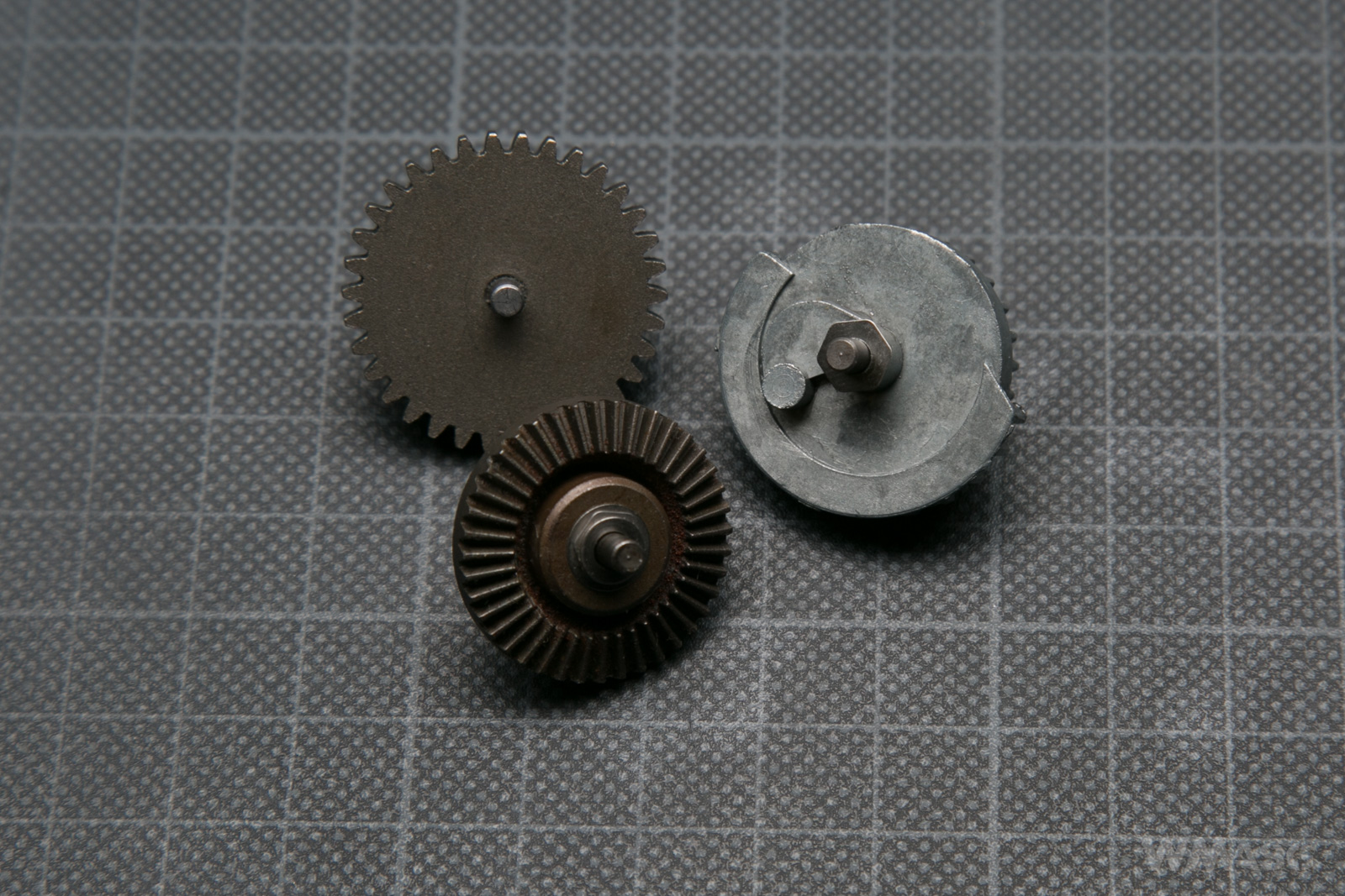
The gears
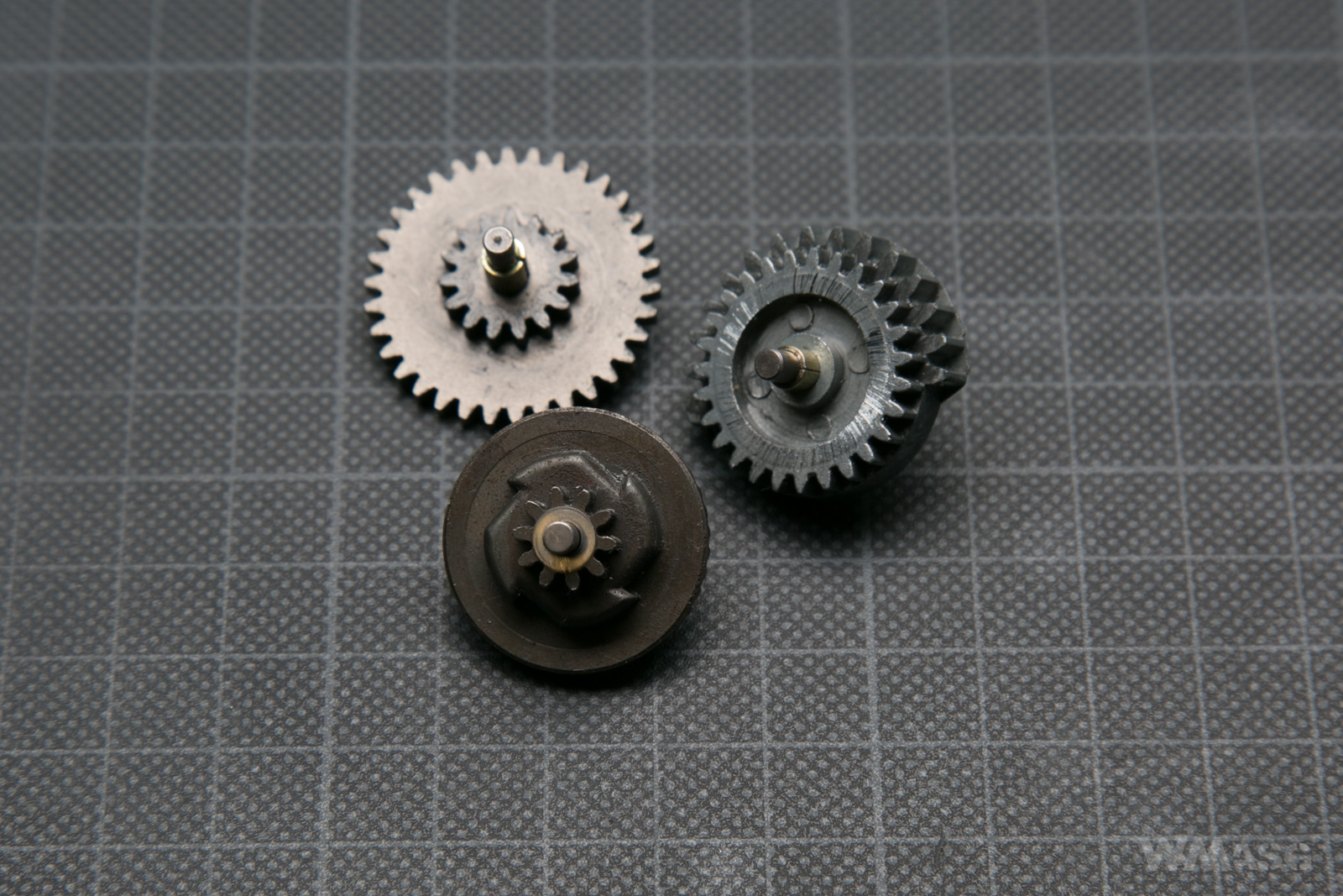
None of the gears fits into the unwritten standard. On the bevel gear the teeth of the anti-reversal latch and teeth cooperating with the spur gear are on the opposite side of the gear than in a usual gear of this kind.
The bevel gear is made of sinters. The others are made of an alloy that has no magnetic properties.
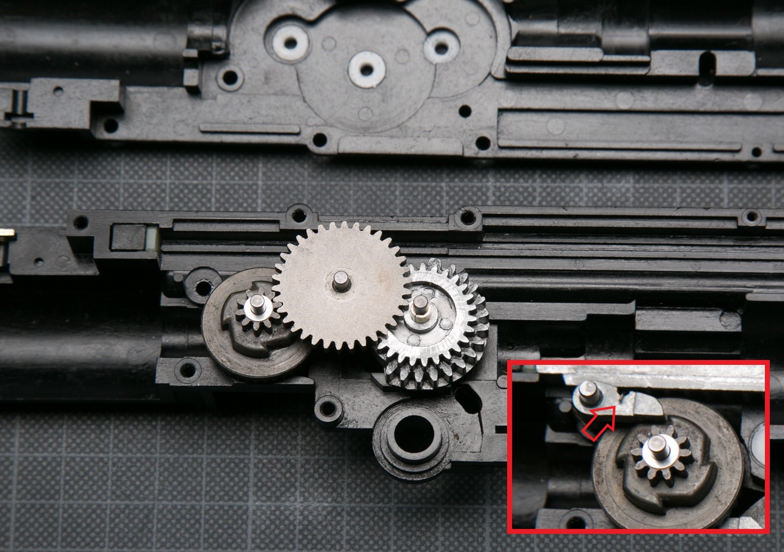
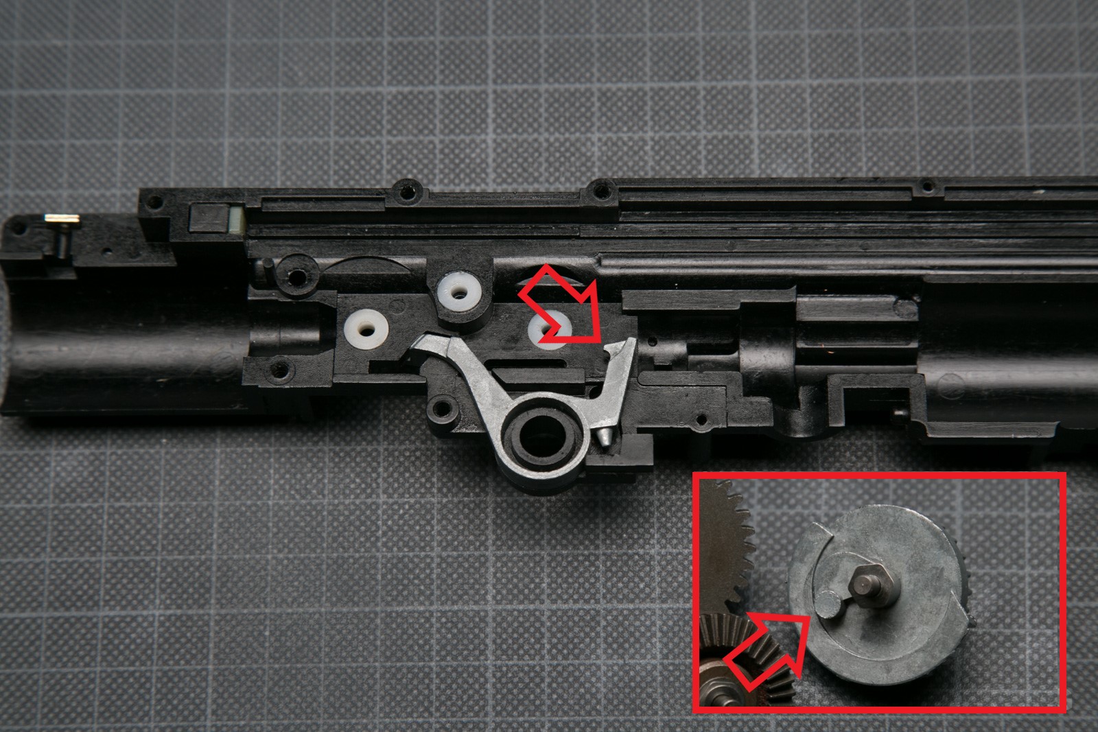
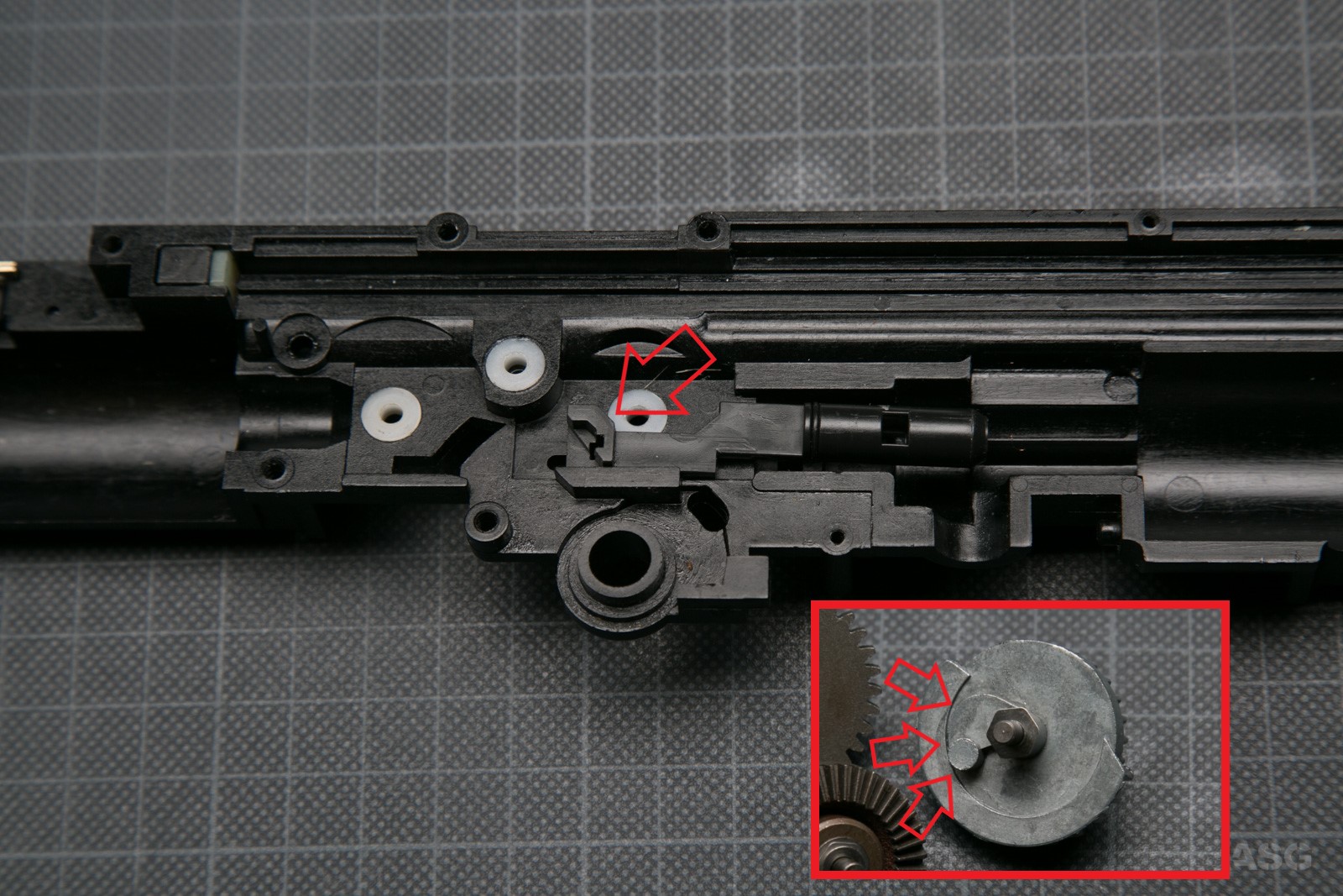
The gears placed in their corresponding places in the gearbox.
And a close up. The miniature shows the location and method of mounting the anti-reversal latch. The marked fragment of the spring is in a special undercut.
The anti-reversal latch with the spring.
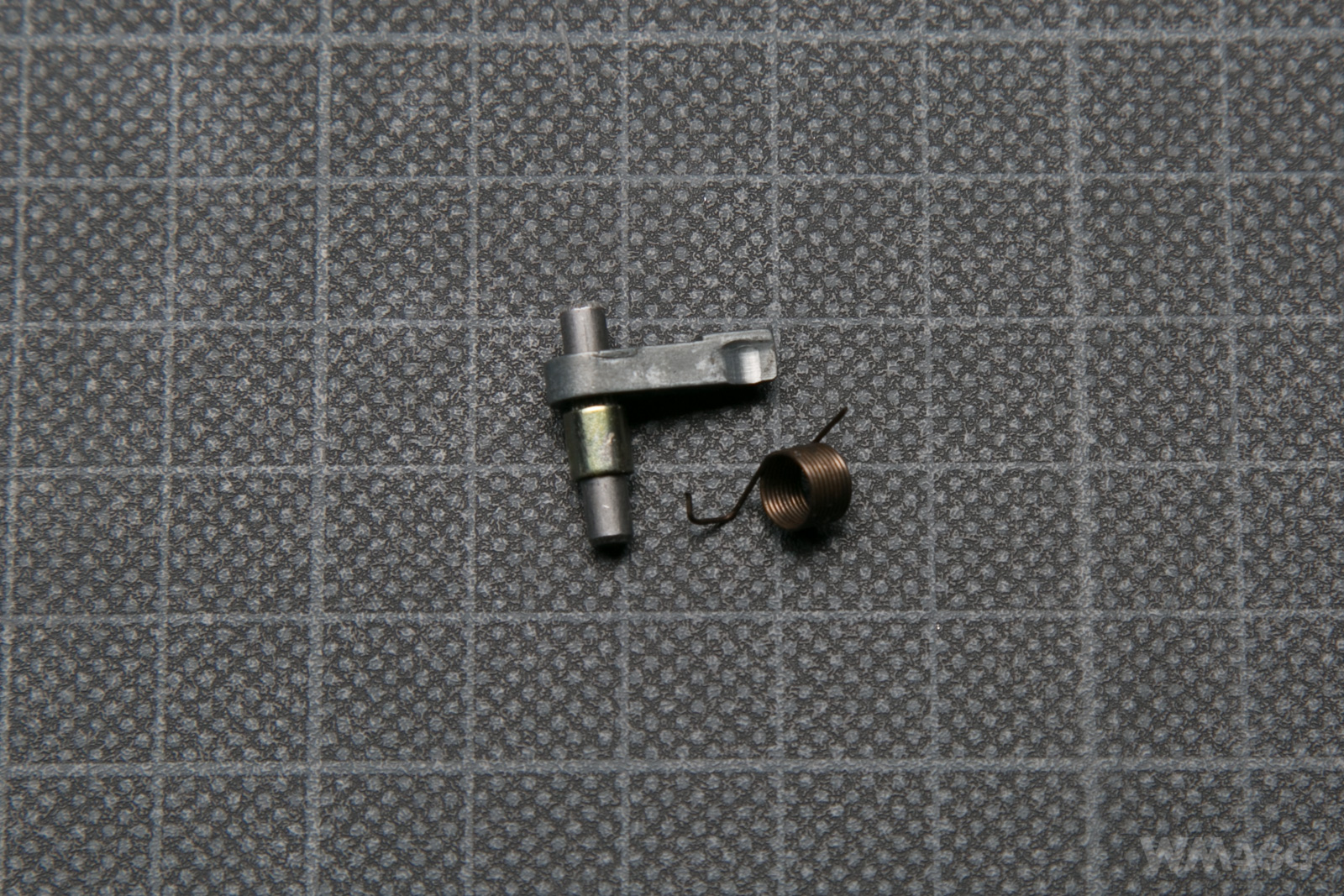
In principle it is identical to the latches used today in other versions of gearboxes. The only differences are the undercut in which the bent part of the spring and the shorter part of the axis sit. It is shorter by about 0.5 mm than the ones currently available. The spring is definitely different. Its arms are shorter and open at a different angle. However, in the case of failure, a standard spring could be fitted.
The undercut visible at the end of the working part in the picture looks quite deep. In fact, it has less than 0.2 mm.
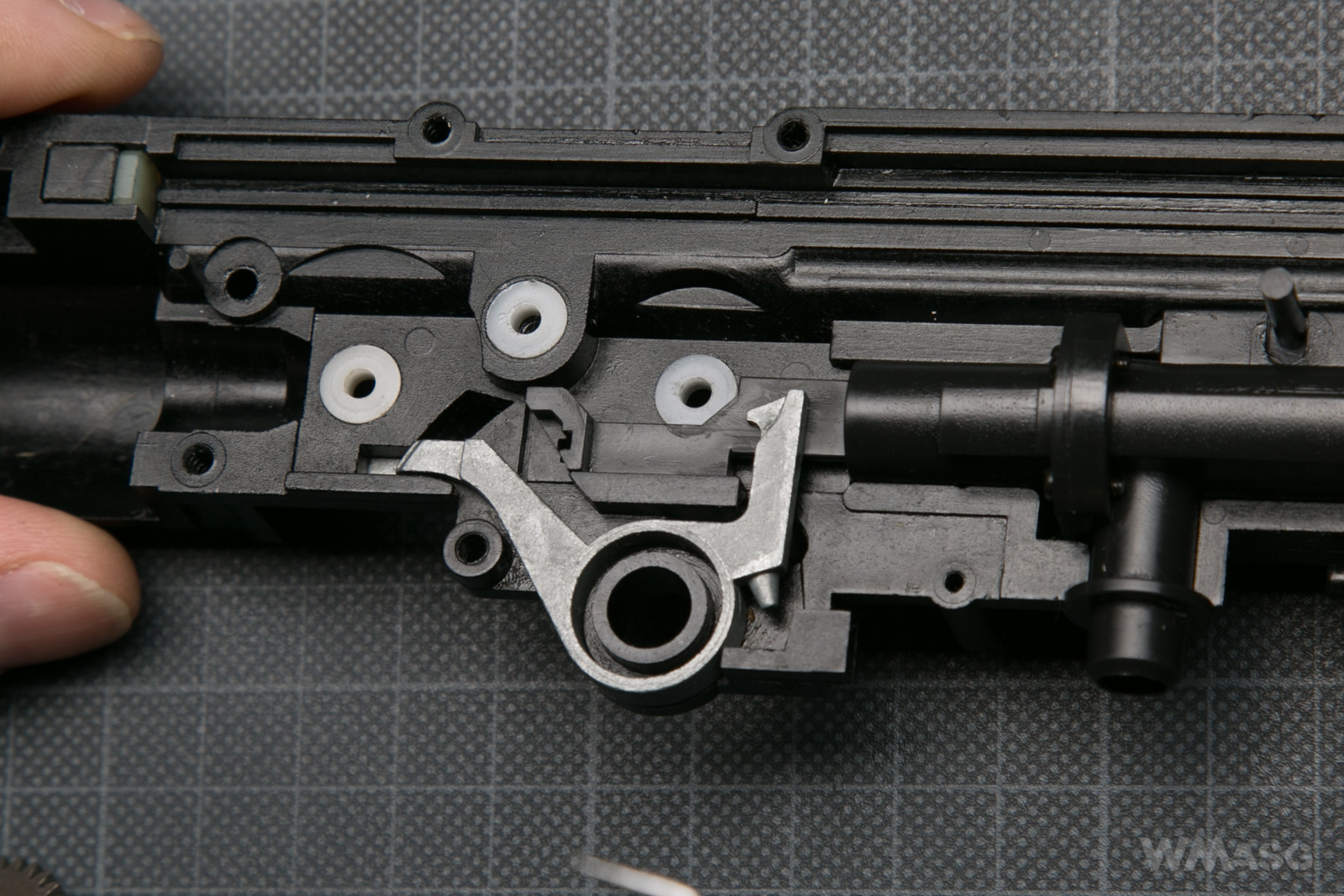
The cut-off lever
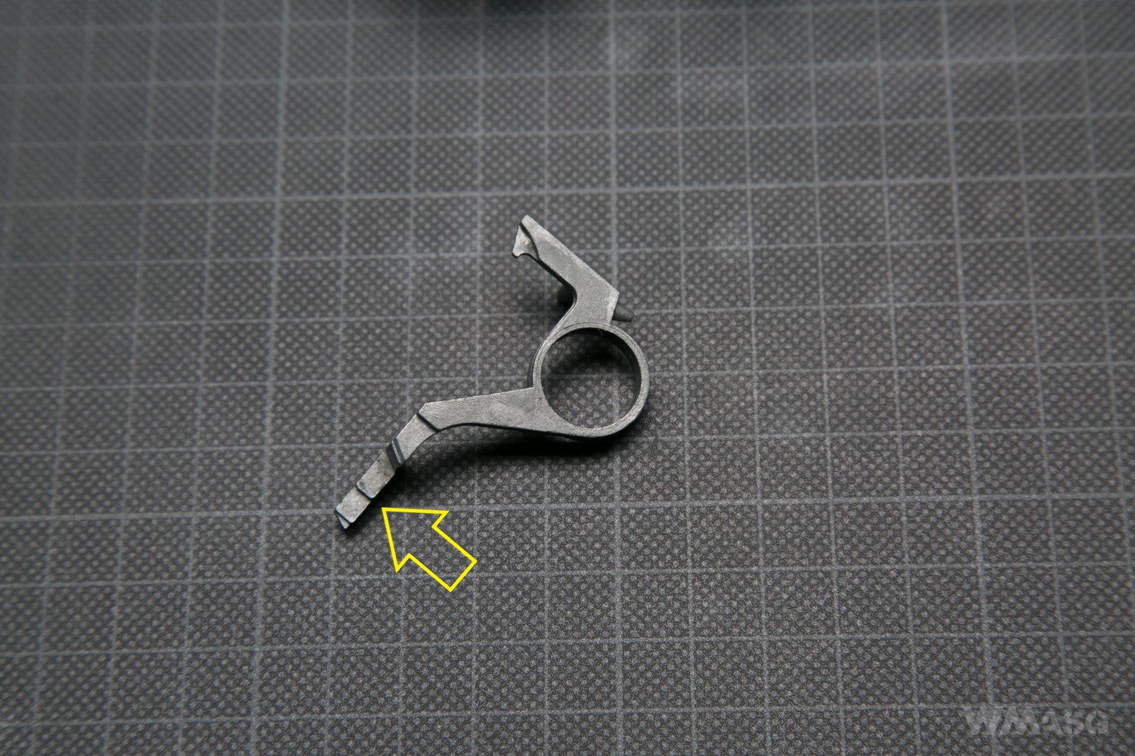
The marked part enters the port in the gearbox and cooperates with the trigger switch located outside. The miniature shows the location of the cut-off lever's return spring.
In the AUTO mode, the left arm is locked in the upper position and does not touch the electrical switch. In the SEMI mode, the sector gear moves with cut-off lever that disconnects the switch. The arrows below indicate the cooperating parts of the sector gear and cut-off lever.
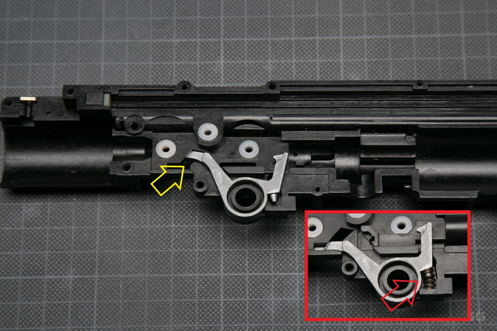
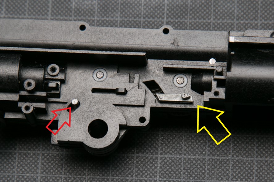
External view from the left side of the gearbox. The part marked with the yellow arrow is the part of the cut-off lever protruding through the port in the gearbox, which disconnects the switch. A smaller, red arrow indicates the latch that blocks the cut-off lever when the fire selector is set to AUTO. In the picture, the cut-off lever in the SEMI position (the latch in the upper part of the port), in the AUTO mode, the latch would be blocked by the selector switch in the lower position, which is not shown in the picture.
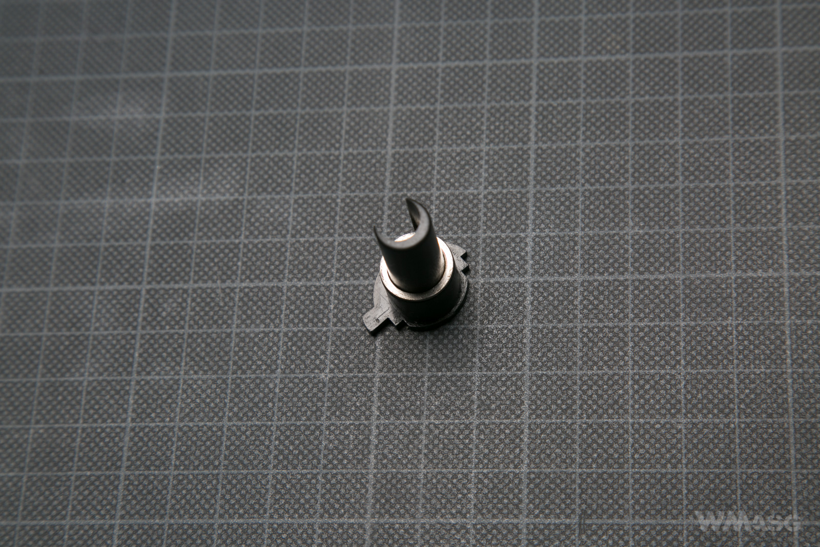
The nozzle. Due to the unique design of the UZI pneumatic system, we will devote much more attention to it than the nozzles of other replicas.
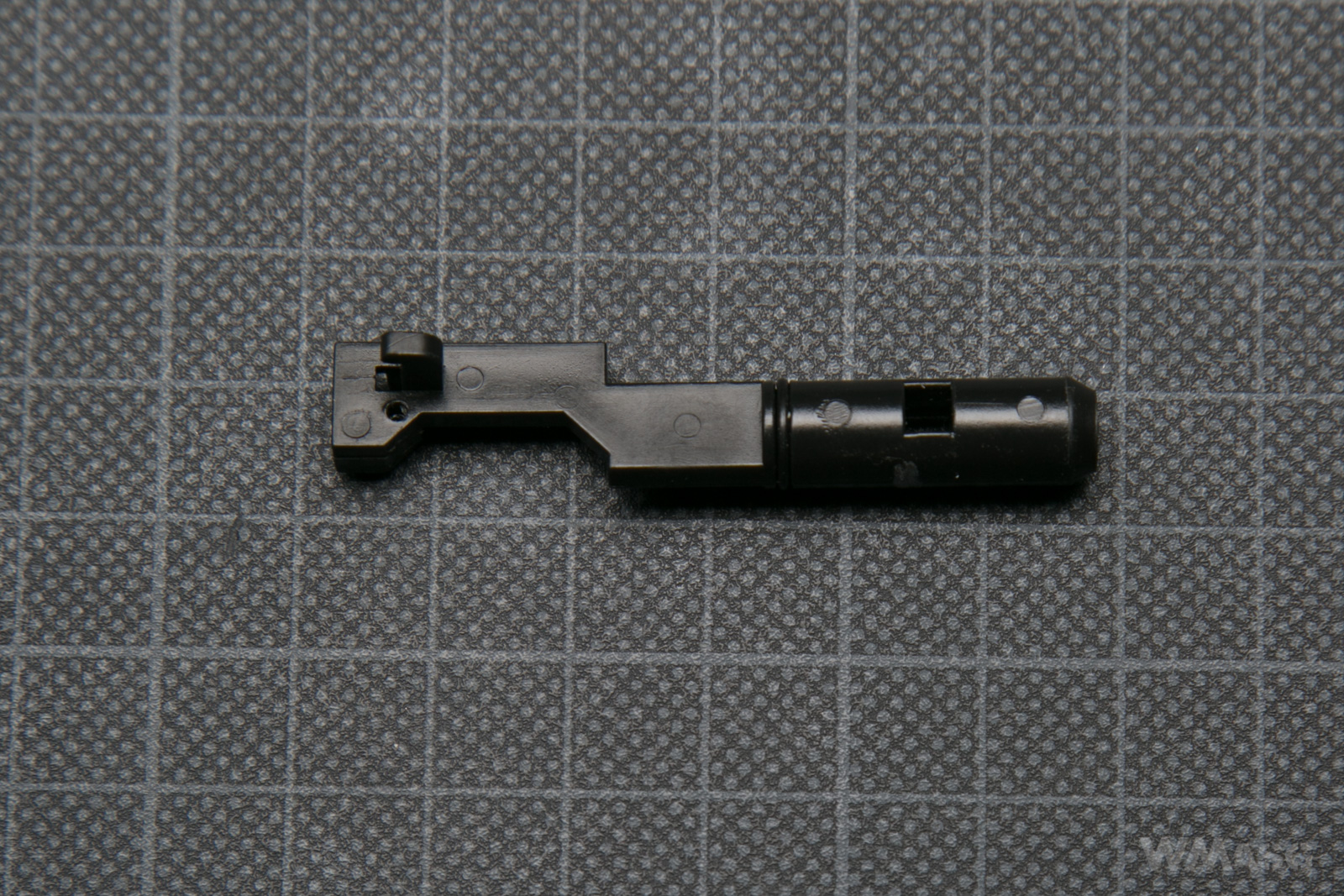
It is made of plastic. As I mentioned - it is a unique design. First of all, it does not work on the cylinder head, it is not even connected to it. The nozzle is an independent part. Secondly, it is directly driven by a sector gear, and not via a tappet plate, which was not used in the UZI at all (in the above photo the nozzle is turned upside down to show the hook used to attach its return spring). Thirdly, the nozzle is sealed. Fourthly, the air directed through the nozzle into the barrel is not pumped into the back of the nozzle but through two ports cut in its walls.
But, first things first...
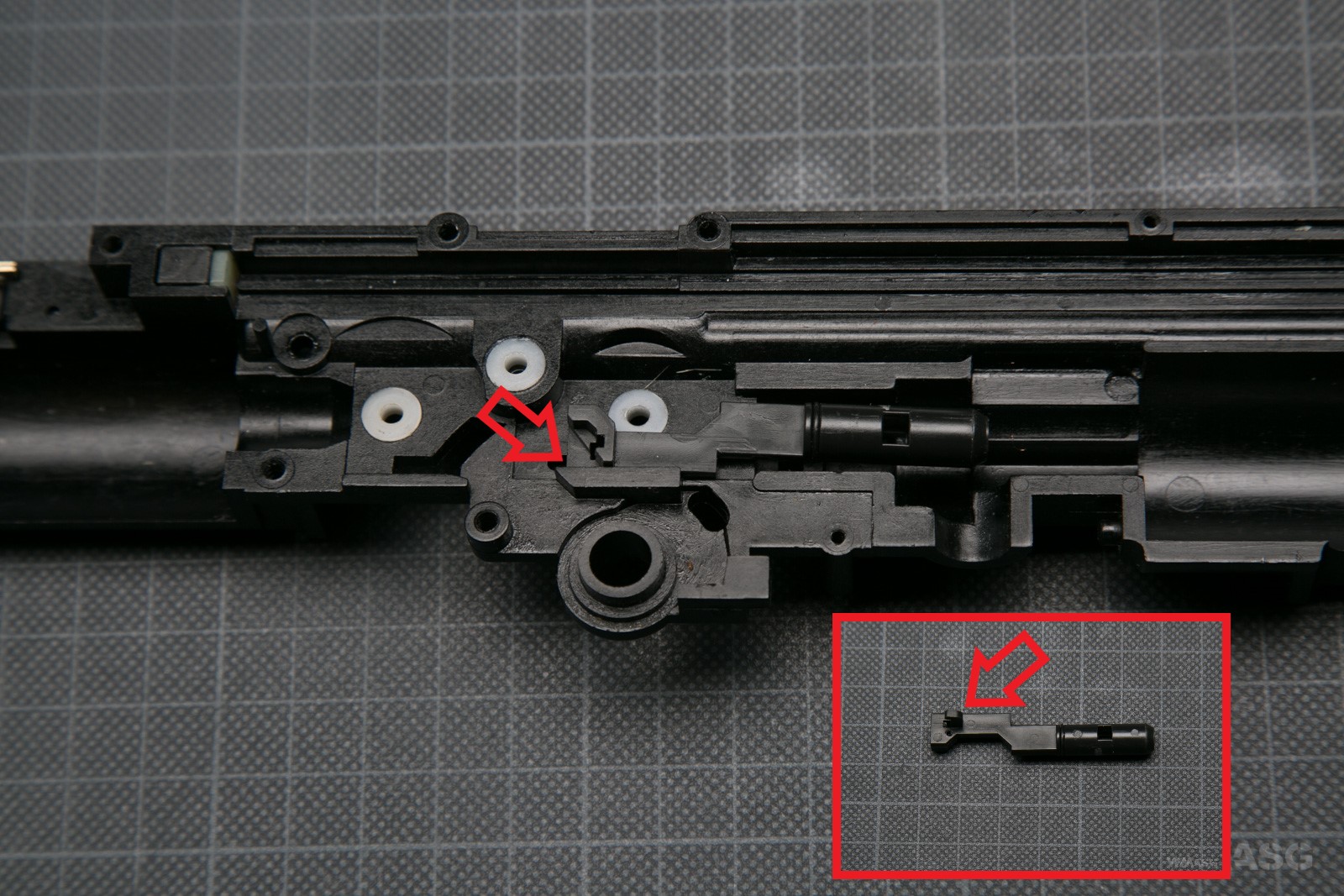
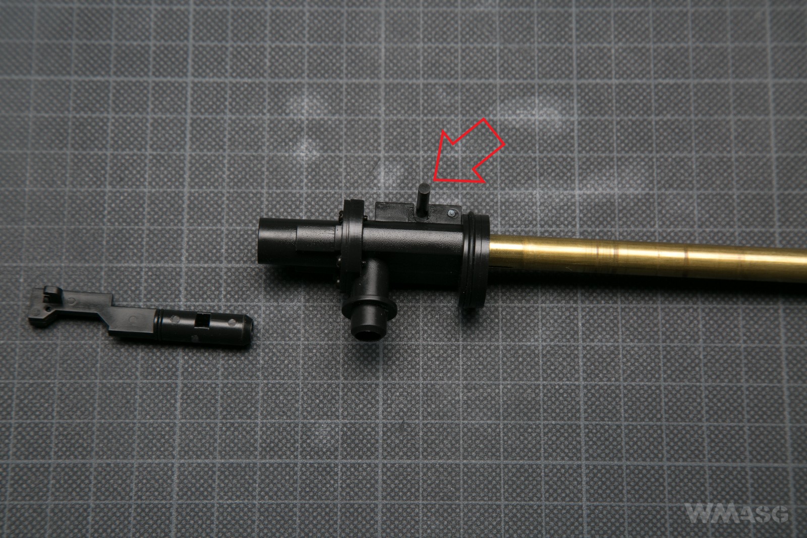
The nozzle in its designated place. The arrow indicates the place where the spring hook comes out of the gearbox (the spring is mounted outside). The miniature shows the hook.
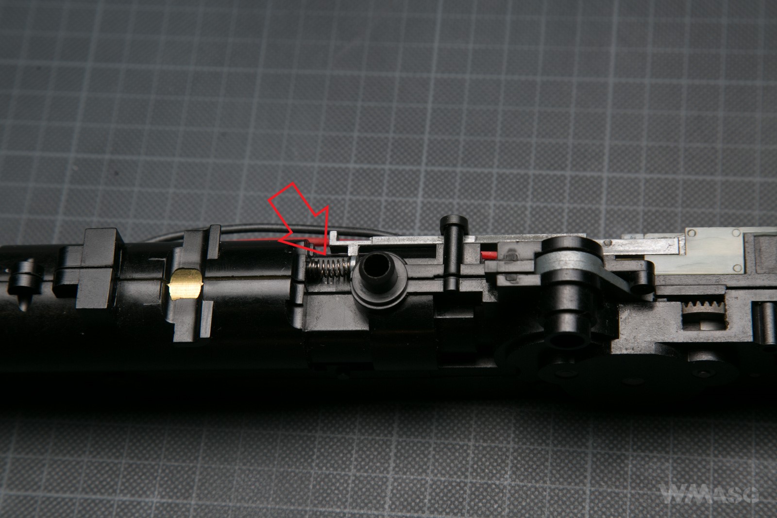
The nozzle's spring and hook seen from the outside. The red arrow is a fragment of the nozzle in the port of the gearbox, when it is completely retracted. The yellow arrow shows the place where the spring is attached to the side of the gearbox. The spring was photographed in the position in which it should be mounted. After mounting the spring, the nozzle hook will move to the left end of the port in the gearbox.

I mentioned a moment ago that the nozzle is moved directly by the sector gear. The picture below shows the nozzle part cooperating with the cam on the gear and on the miniature the working edge of the gear.
One rotation of the sector gear retracts the nozzle and lets the BB feed by the magazine in front of the nozzle. After cam on the sector gear moves further, the nozzle returns to the front position pulled by the spring shown in the two photos above. Moving forward, the nozzle feeds the collected BB into the HopUp chamber. The shot is fired when the nozzle is completely in the front position. Then the cycle starts anew.
As a rule, the nozzle and cut-off lever cooperate with the sector gear in the same way as in any other gearbox. The difference is the lack of a tappet plate in the discussed design.
The nozzle and the cut-off lever in their working positions. A part of the nozzle hidden in the HopUp chamber.
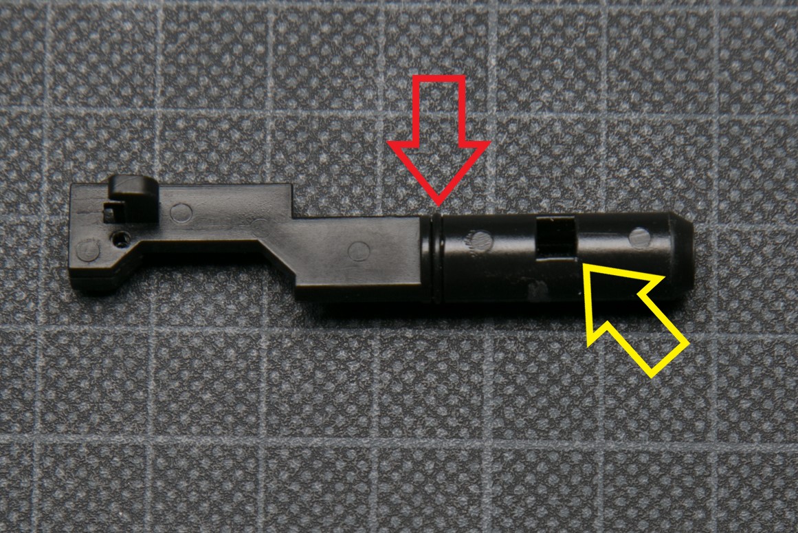
The aforementioned sealing (an o-ring) and the ports, through which the air compressed in the cylinder enters the nozzle. The second port is placed symmetrically. It is on the other side of the nozzle.
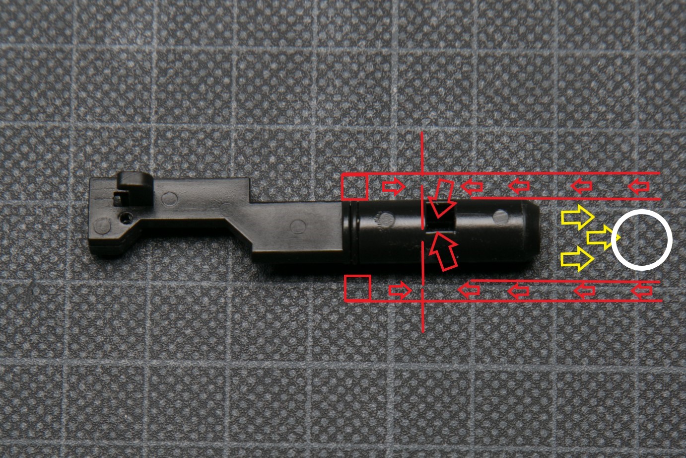
What are these ports for? In the diagram below, the red lines are the walls of the HopUp chamber. The air compressed in the cylinder (red arrows) passes through special air ducts in the chamber from the front. Since the back of the connection between the chamber and the nozzle is sealed with the O-ring, the air does not go any further but enters into the port inside the nozzle. The vertical dashed line indicates the place where the baffle is inside the nozzle. The only possible direction of the air movement is through the outlet of the nozzle (yellow arrows). Of course, there is a BB along the way, and then the barrel.
Of course, the proportions and dimensions are disturbed on the diagram. In fact, HopUp chamber air outlets almost perfectly aligned with the nozzle windows when it is in its most forward position. Then the piston is released, the pressure in the cylinder increases rapidly, the air flows through the channels, enters the nozzle and accelerates the BB.
The HopUp chamber
From the description of the nozzle and its operation it is already possible to roughly deduce how the chamber is built.
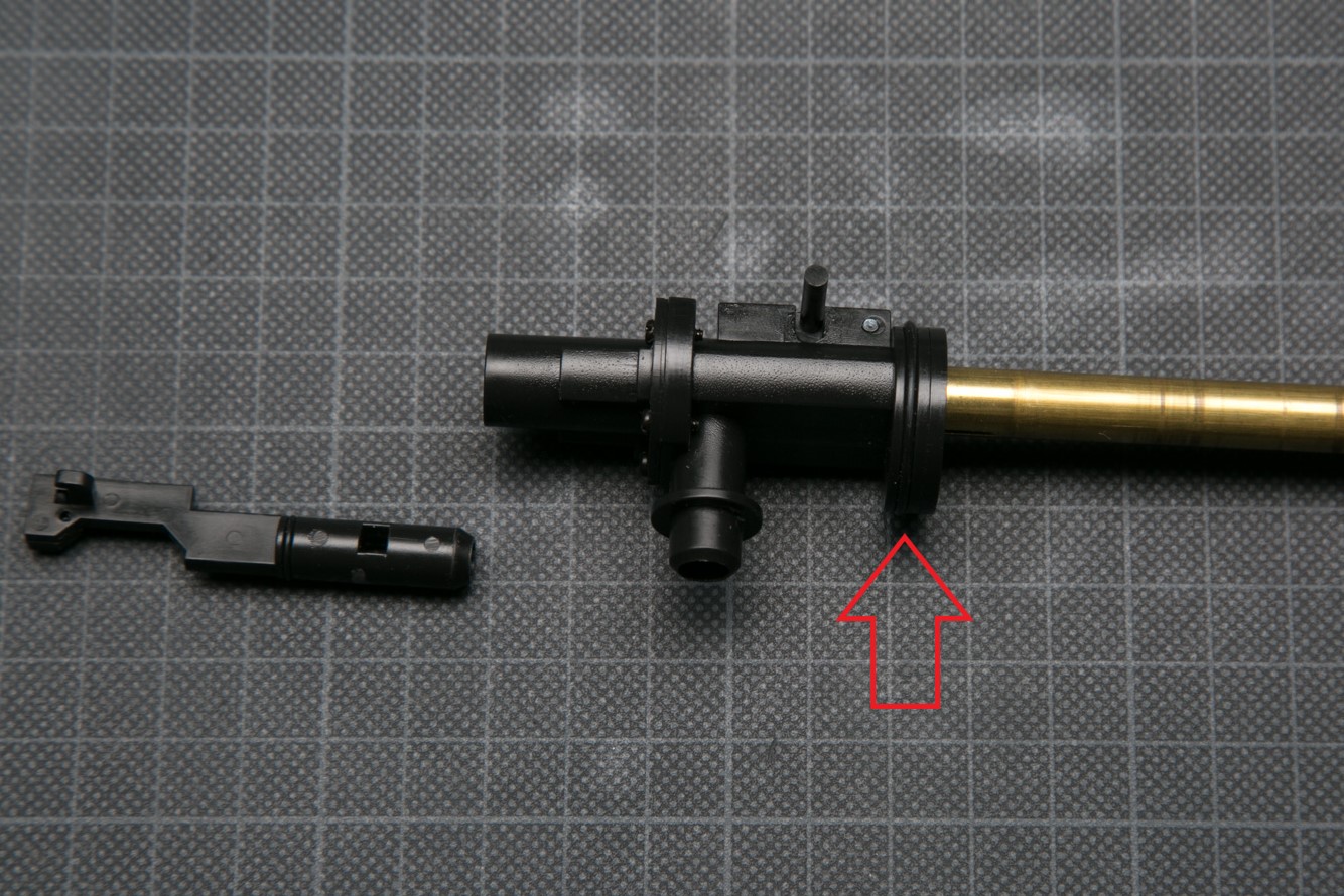
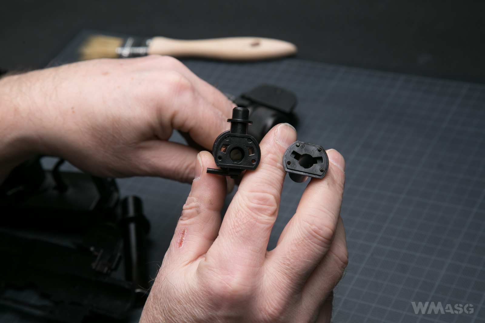
First of all, the chamber is also acts as a cylinder head. Above, the arrow indicates the location of the o-ring sealing the cylinder-chamber connection. Below, the air ducts of the chamber are perfectly visible. This is the part the piston strikes and pushes the air into the channels. It is worth mentioning the this part has no bumper of any kind.
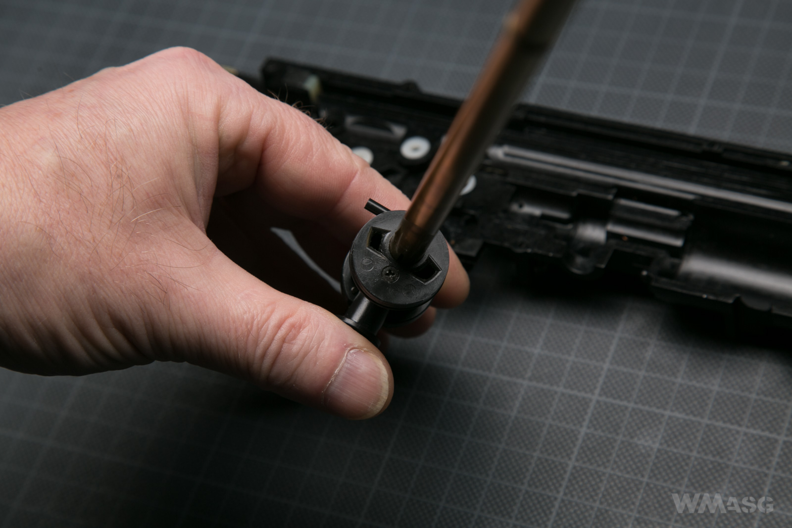
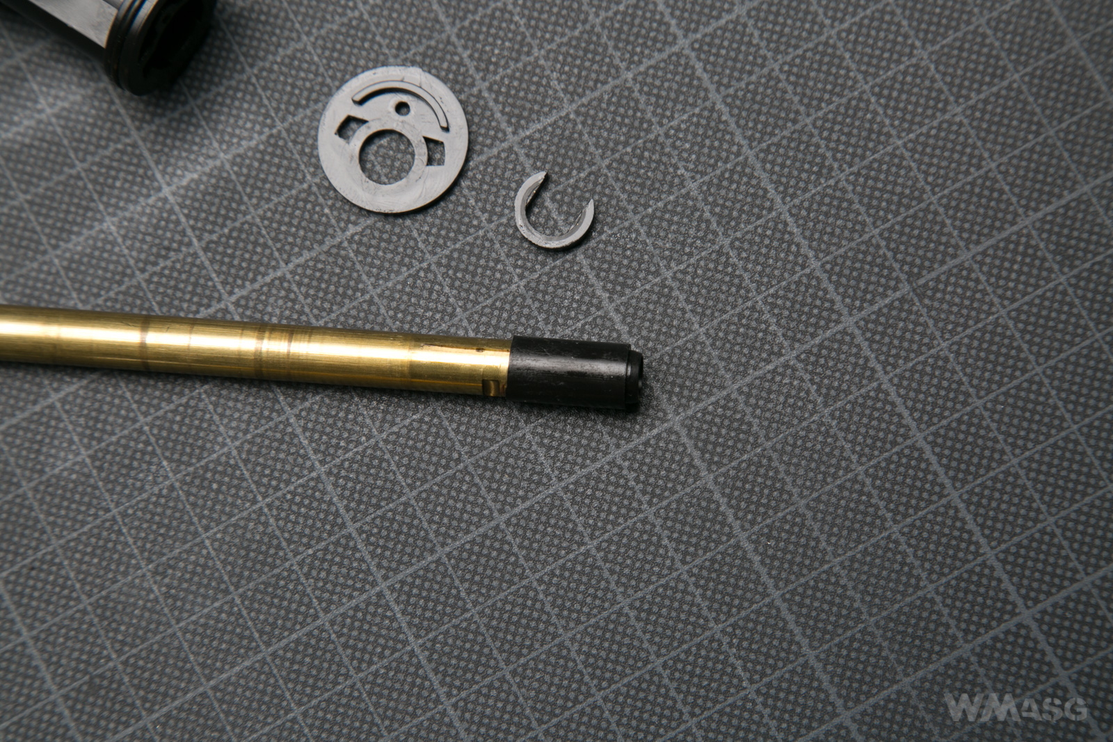
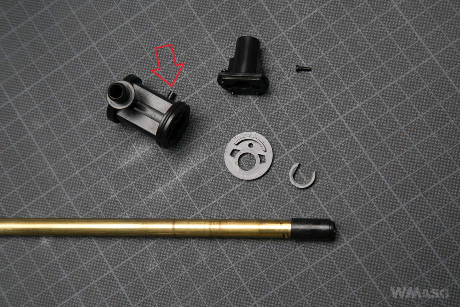
By unscrewing the screw visible above, you can remove the "bottom" of the chamber. Then access to the clip holding the barrel in the chamber is obtained. After removing the clip, you can pull out the barrel with the bucking. It is the same kind as the ones used in AEGs.
You can also disassemble the second part of the chamber, the one from the side of the nozzle.
On the left, the part with the barrel and the bucking, on the right, the part in which the nozzle works. In the left part open air channels are visible. In the right, you can see the where they end. This is where the nozzle windows stop.
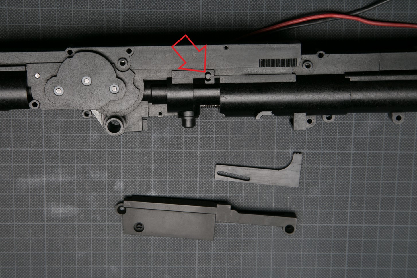
The chamber disassembled almost to its basic components. The marked part is a fragment of the classic swivel pressure arm cooperating with a standard tubular spacer.
Here is the same fragment of the pressure arm. It is that part which moves the lever with the spacer during the adjustment of the HopUp system.
The design of the HopUp adjustment mechanism. The marked part was described above. Next to it is the adjustment lever and securing part.
The adjusting lever is in its place. The teething prevents the system from deregulation.
And lever with protection on. Only the assembly screws are missing.
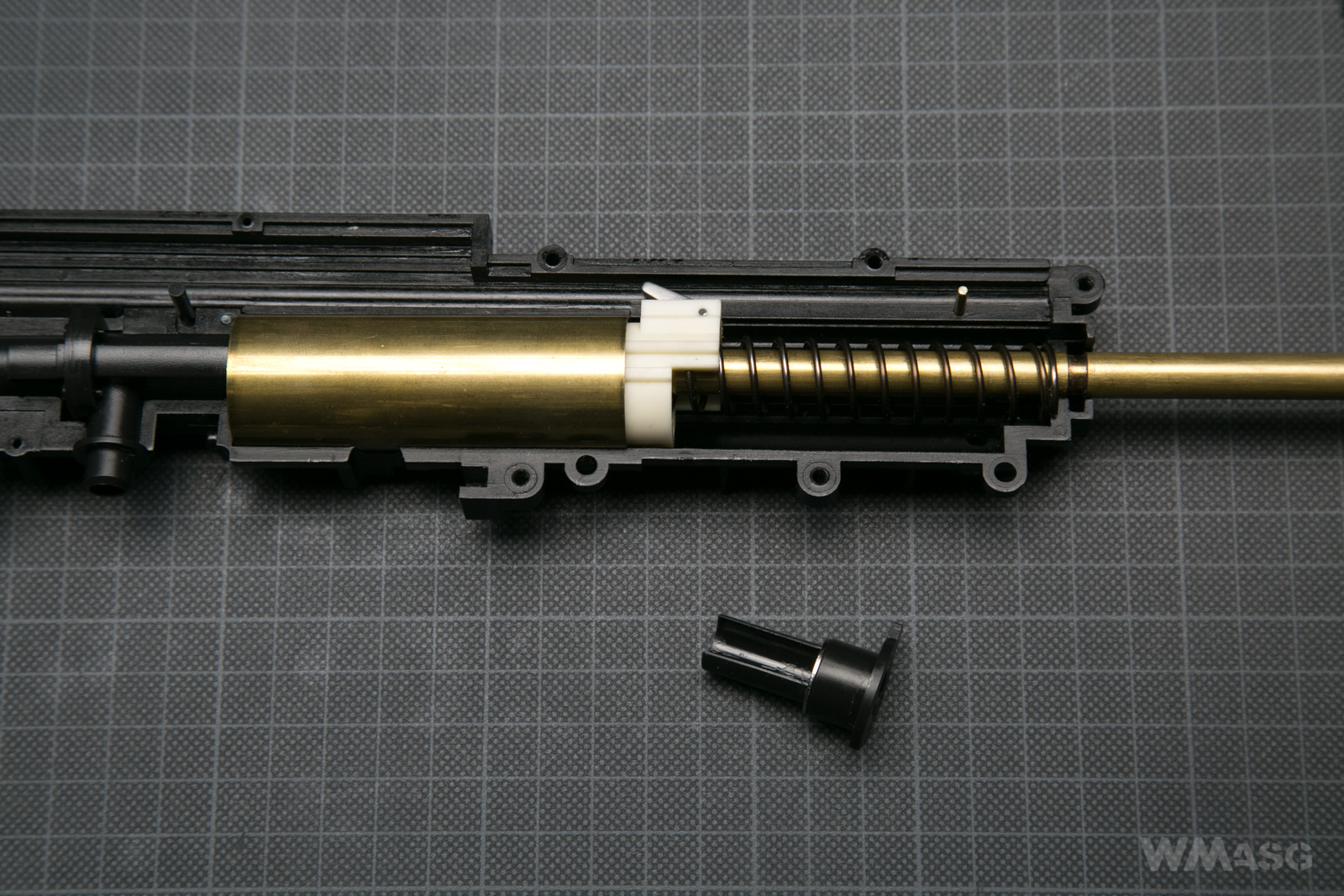
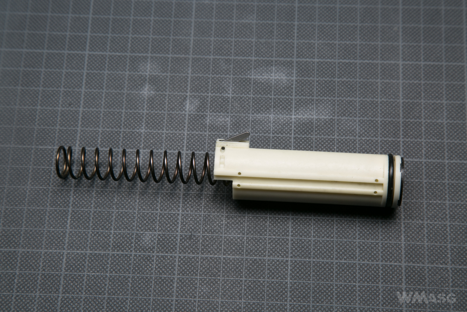
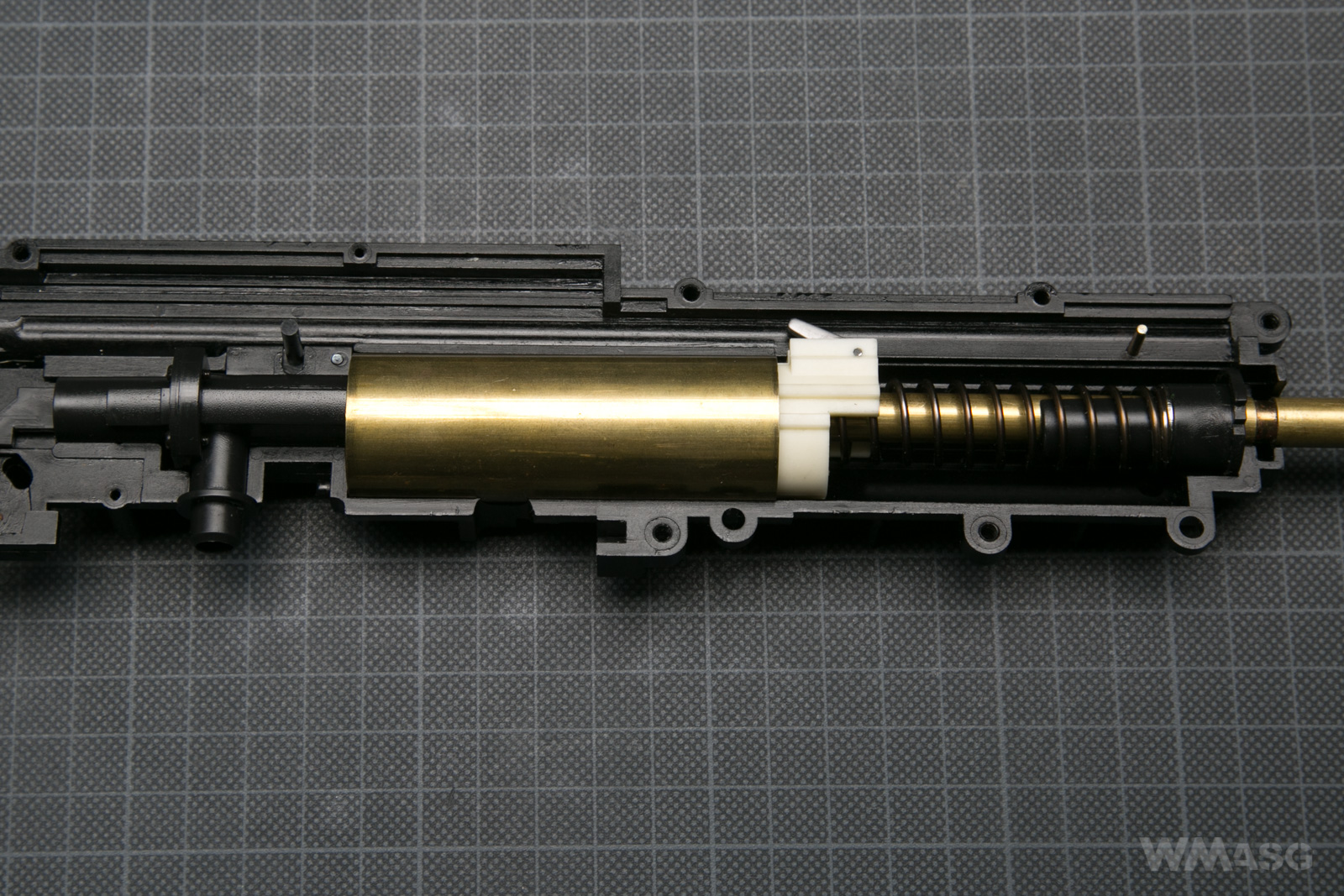
The piston set in its working position:

From the left: the HopUp chamber acting as cylinder head, the cylinder with piston inside, the main spring, the spring guide. The barrel runs through the center.
Let's start from the right side.
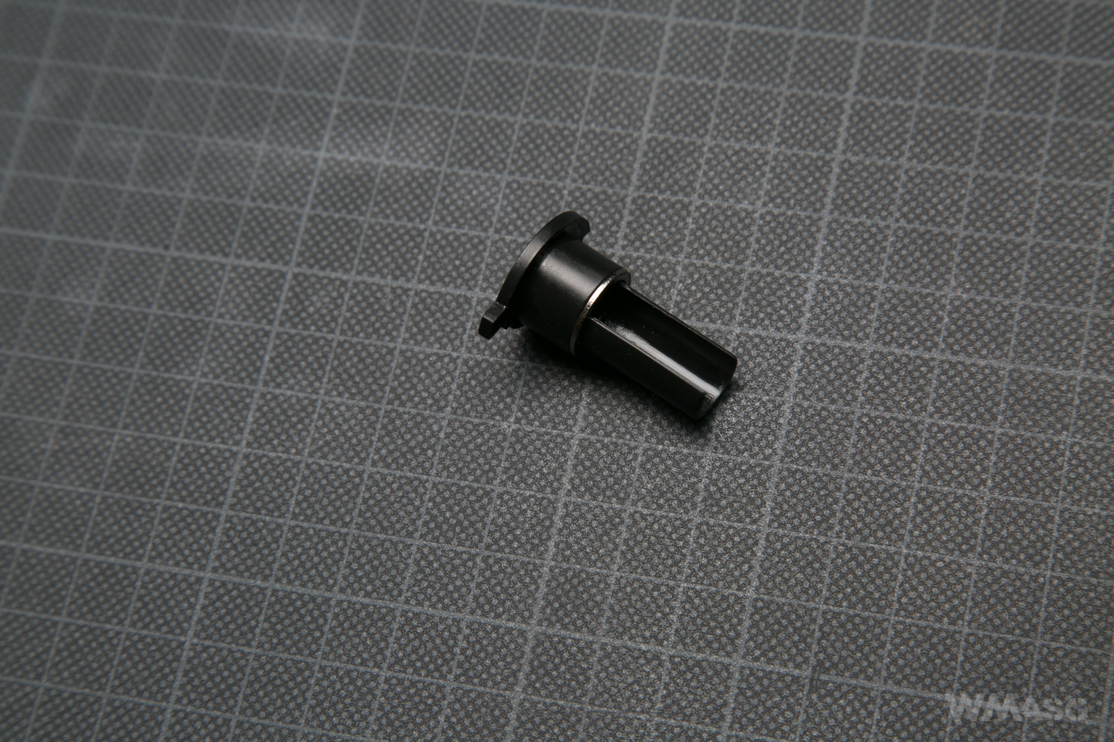
The spring guide made of plastic. It is already dismantled here. The protruding part of the base enters a special notch in the gearbox and keeps it in the right place.
The piston
A standard sized piston with one steel tooth made of polymer. As in all (until recently) replicas made by Marui, the spring has been permanently attached to the piston.
In the rear part pf the piston, at the top, is a hook for the previously mentioned rod. The solution is a bit similar to some EBB replicas. Here, however, the hook is made of metal, has an axle and a spring, thanks to which it returns to the upper position (as in the picture).
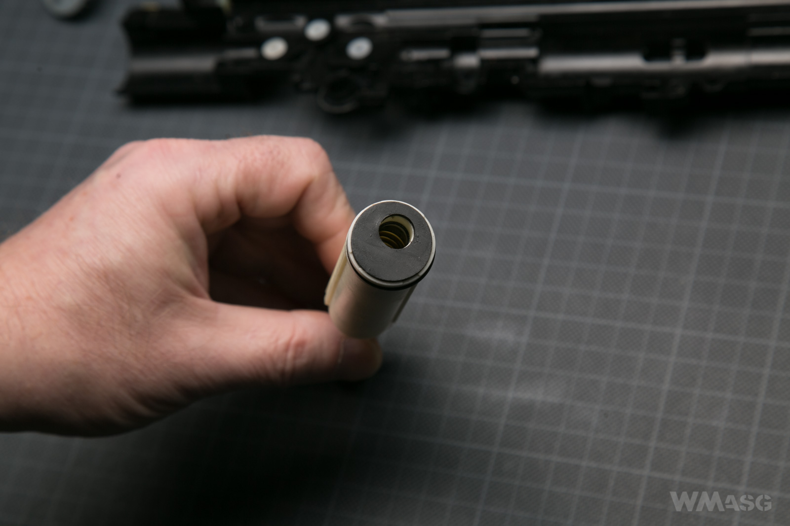
Miracles, however, start when we look at the piston from the front:
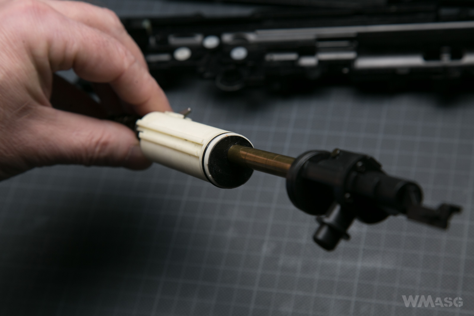
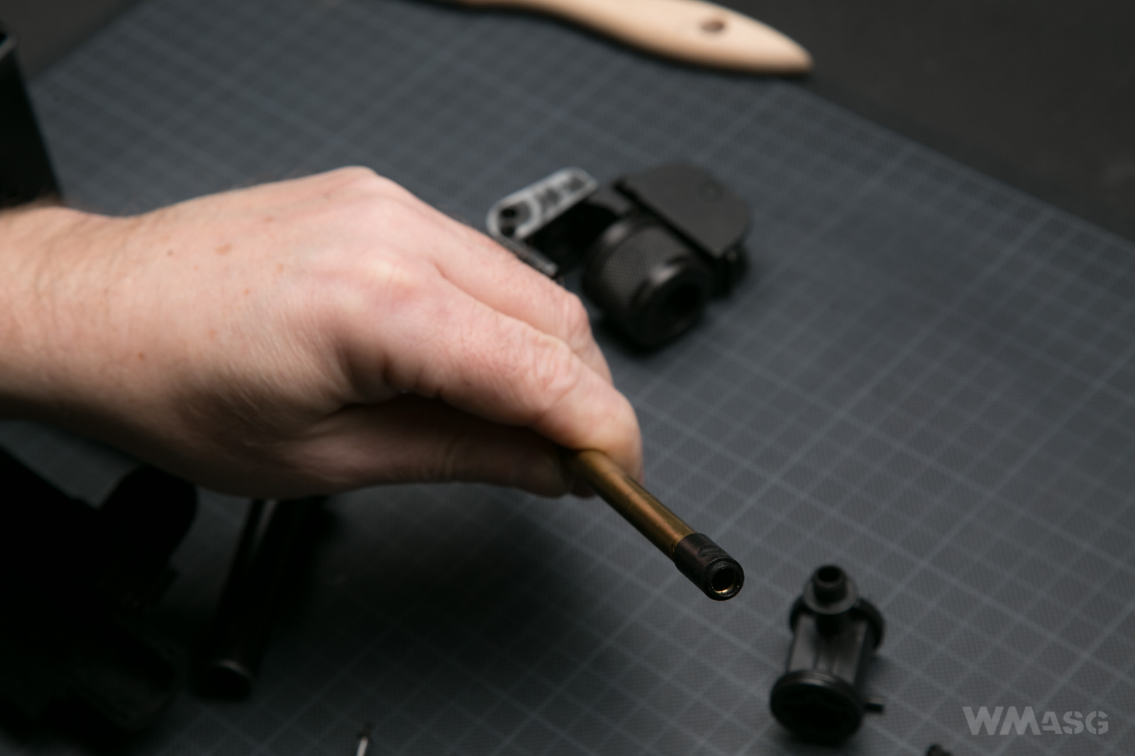
Yes, the barrel passes through the piston head. This is the second time that the barrel's axis does not coincide with the cylinder/piston axis (which is no longer shocking - see the P90, the M14).
The front part of the piston has a glued rubber bumper. This is, again, an inverted design. In most gearbox versions the bumper is on the cylinder head. A regular O-ring is responsible for maintaining the tightness. There are no holes to improve the air tightness of the O-ring.
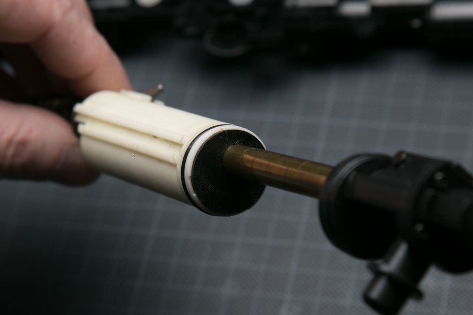
There is an additional seal in the hole through which the barrel passes.
How does the piston move?
The piston in the most forward position (i.e. it rests against the bottom of the cylinder):
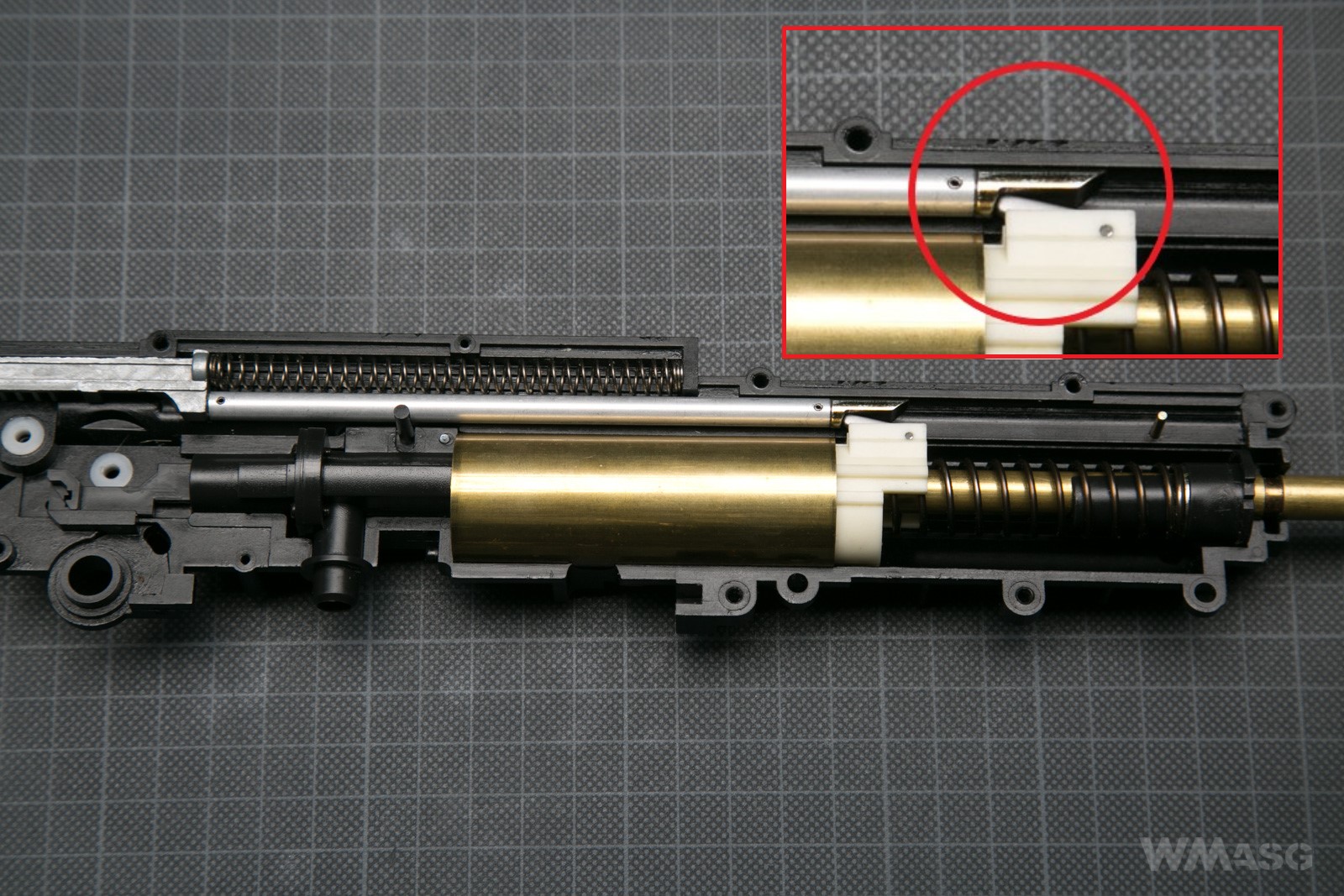
Now with with rod and its return spring. Pay attention how the rod engages with the movable tilting hook on the piston's top.
The other part of the rod:
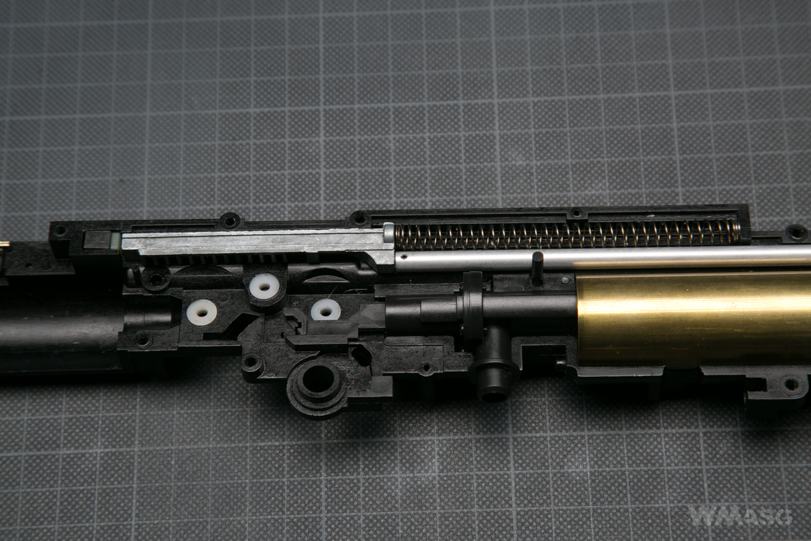
Here a better visible toothed rack that works with the sector gear:
Here, in turn, you can clearly see how the rod and the sector gear work together. The spur gear was taken out for greater image clarity. Also the direction of rotation of the sector gear and the direction of the rod's motion are shown with red arrows:
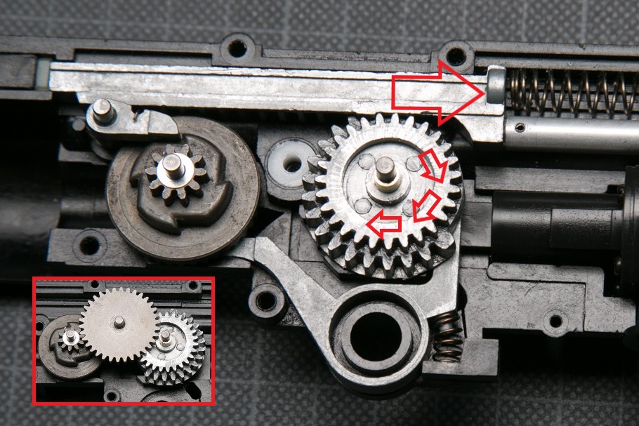
The rotation of the gear causes the sector teeth to engage with the rack and in turn move the rod. This pushes the piston forward towards the barrel exit until the piston latch is pushed under the steel pin embedded in the gearbox (yellow arrow).
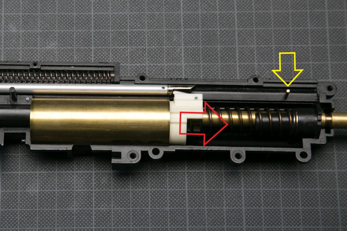
At this moment the rod and the piston are disconnected. The piston, driven by the main spring, moves in the opposite direction. The shot is fired. At the same time, the toothed rack disengages from the teeth of the sector gear. The rod is pushed back with its return spring into its initial position. The cycle can start anew. Of course, the rotating sector gear synchronizes the movement of the nozzle and the feeding of the BBs with the movement of the piston.
The motor and trigger switch
The replica is powered by a standard short motor.
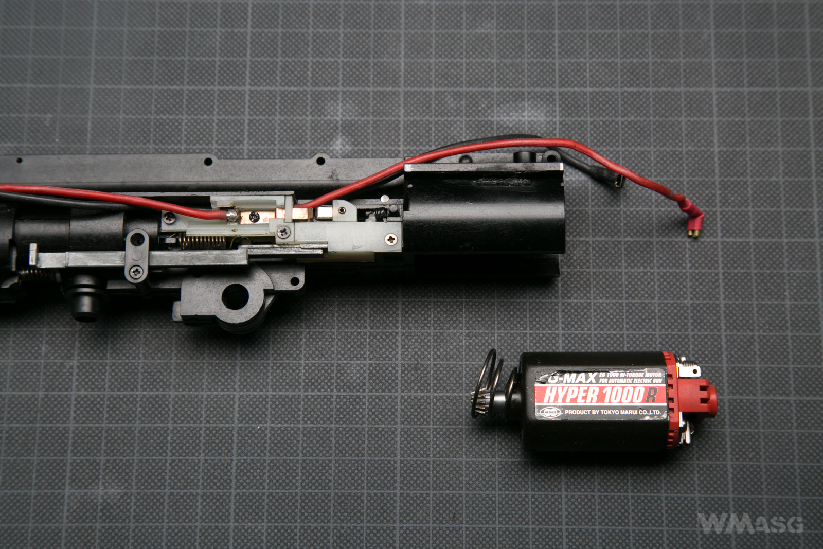
The motor in its place in the gearbox.
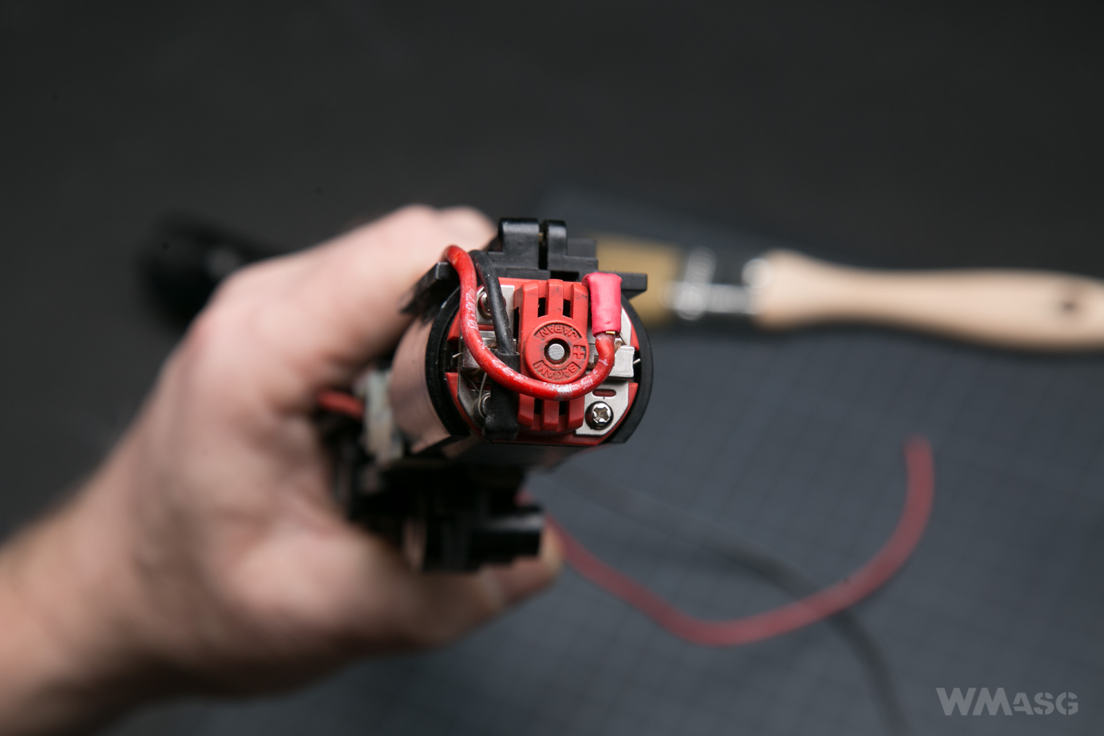
The motor mounting part is the rear wall of the replica's receiver. A spacer washer is installed here. In the center of the part there is an Allen screw used to adjust the motor.
It is only after installing this part that you can try to start the mechanism. Of course, you can also try it without assembling the replica and holding the motor with your hand. It's just that spare parts for Uzi, including gears, are virtually unavailable.
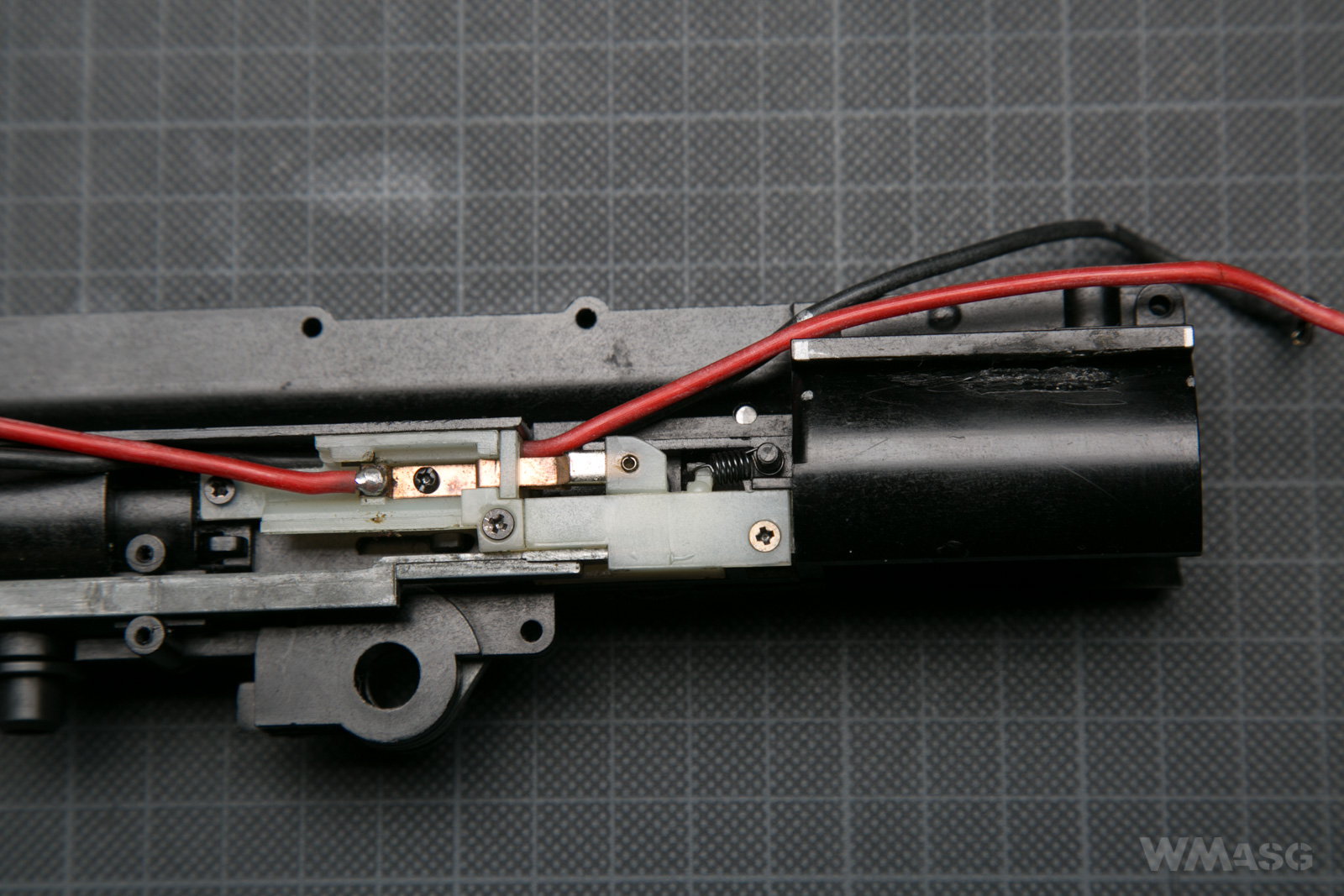
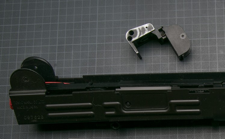
The trigger switch and the wires
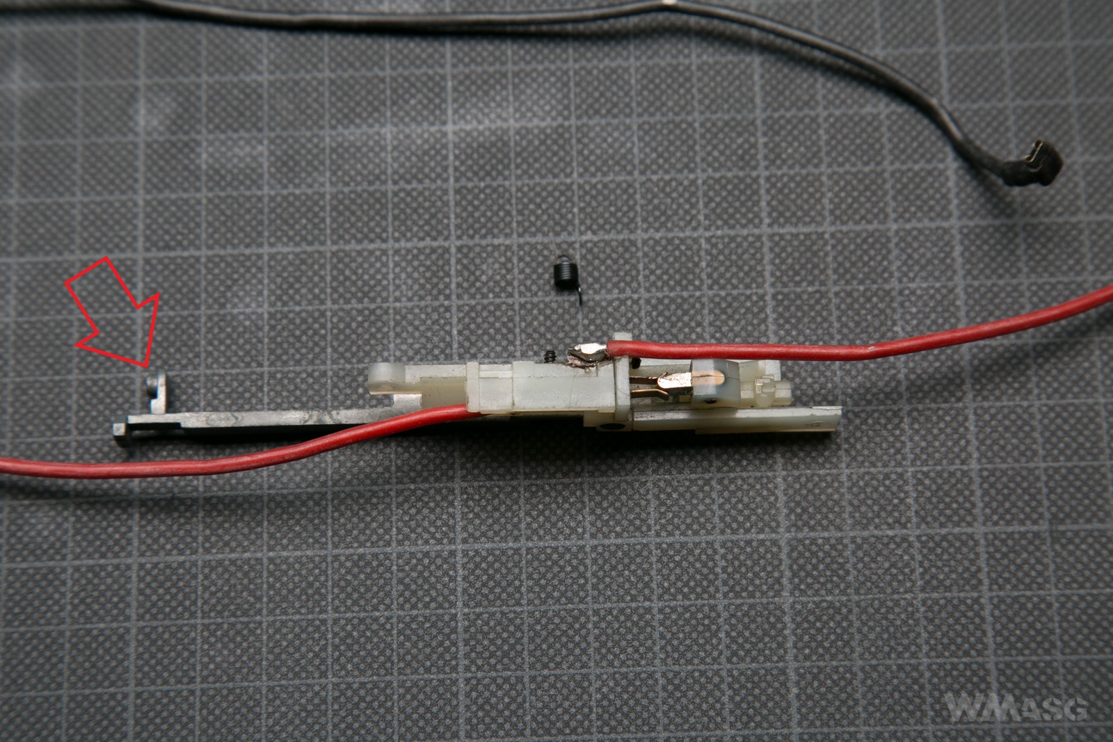
The trigger switch is placed outside of the mechanism on the left. The screwdriver indicates the place where there should be one more screw holding the lever that carries the movement of the trigger into the switch. The previous owner must have lost her.
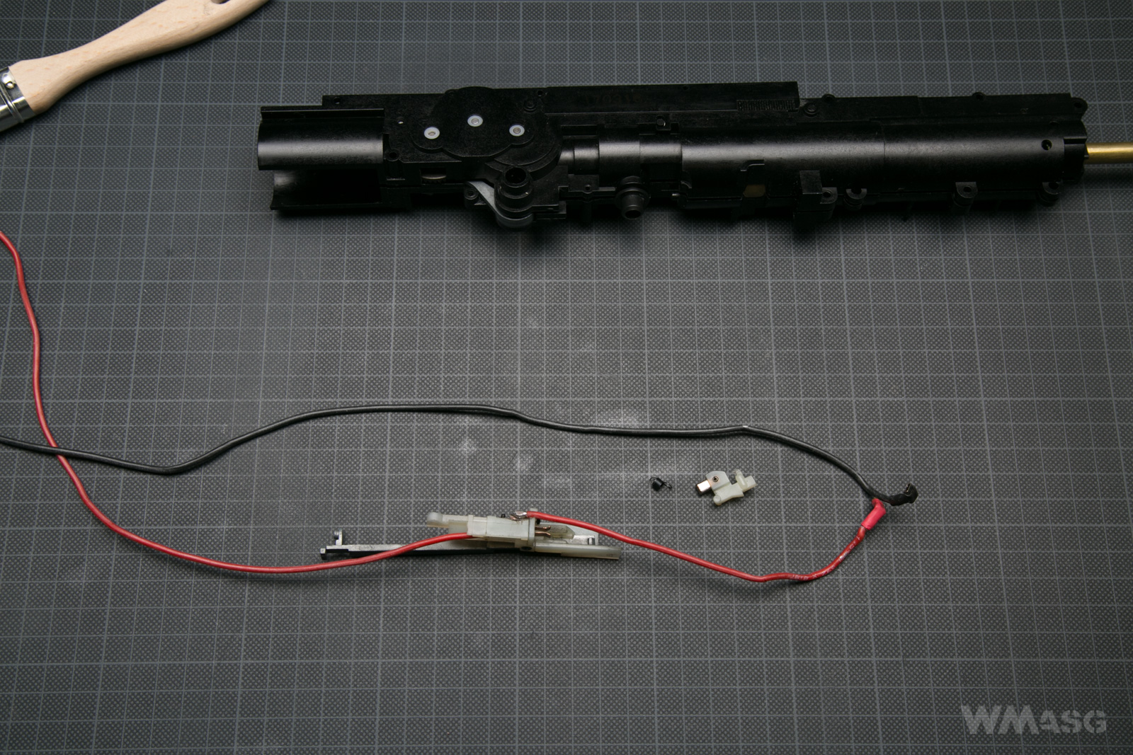
The shape of the trigger switch and the parts working with it are non-standard.
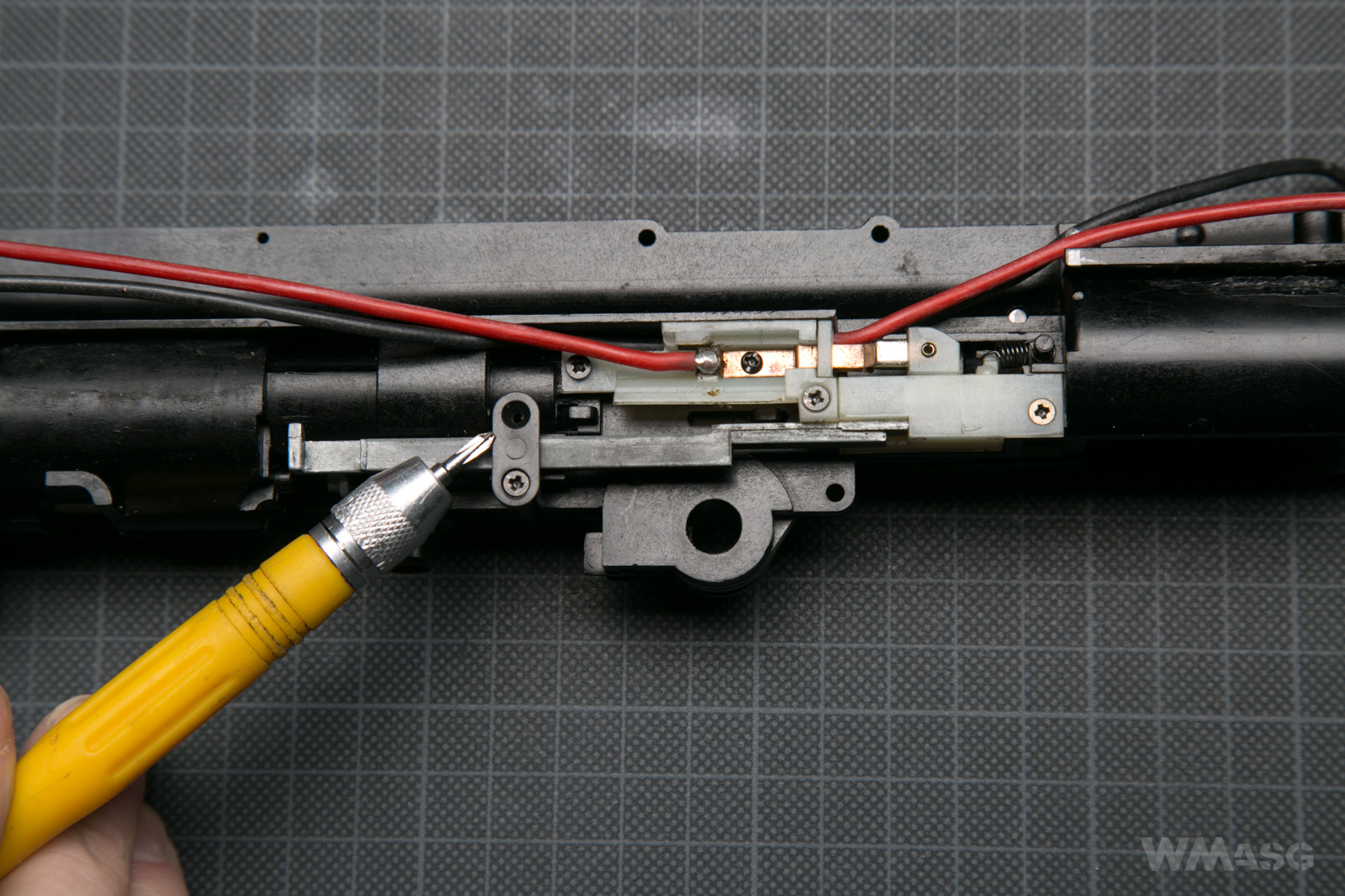
I have marked the place where the return spring of the switch pusher is attached.
View of the mounted switch and the return spring of the pusher.
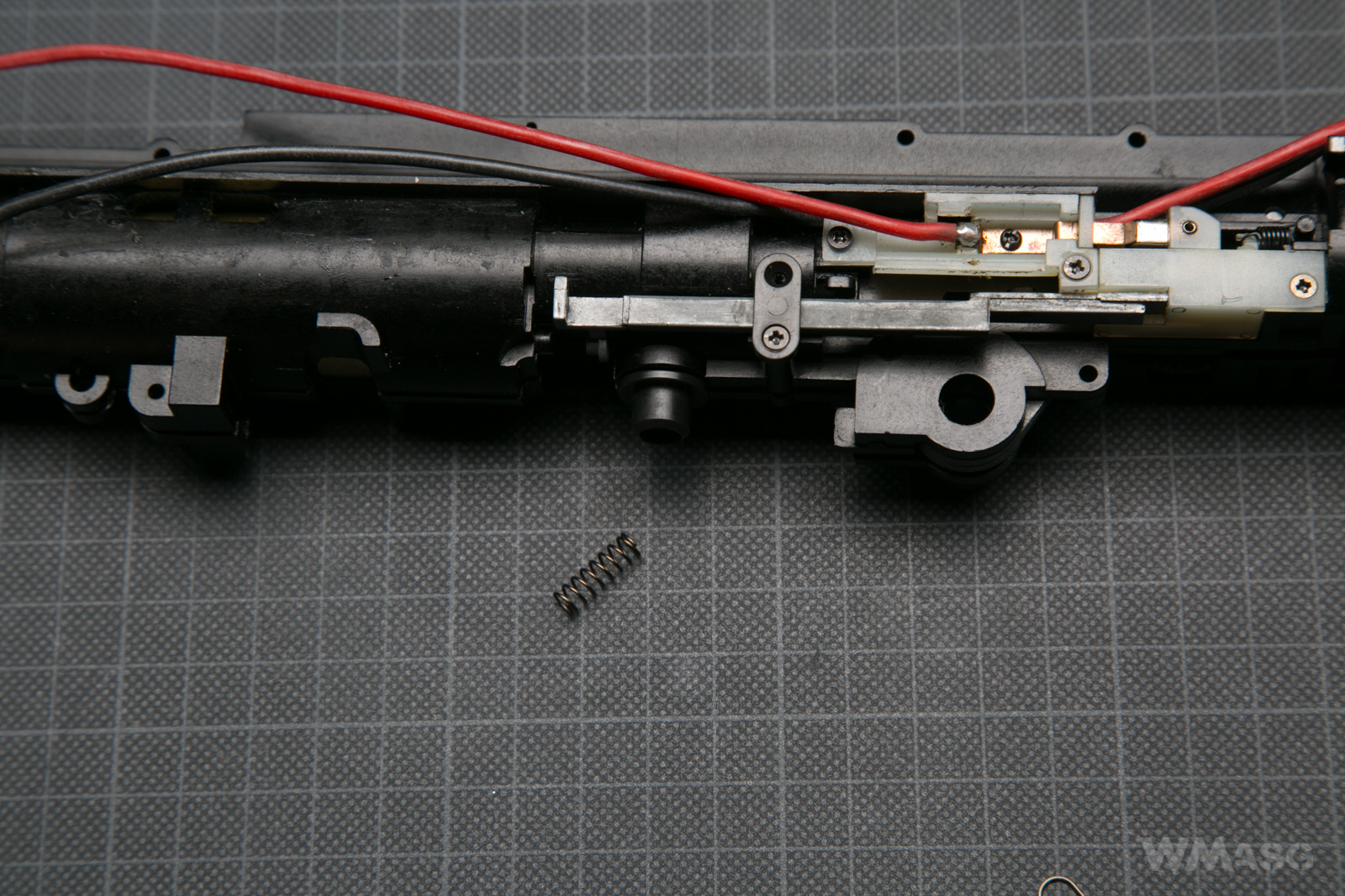
And the spring in the right place, next to the BB feeding tube.
The wires visible on the above photos are not original. The factory made wires were thin and rigid, covered in hard insulation. The whole electrical system was protected by a cartridge fuse. In the described unit, somebody has replaced the wires with thicker ones and removed the fuse. In practice, the wires used are too thick. Putting them into the pathways provided by the factory is basically impossible and poses a risk of mechanical damage to the insulation. When assembling the replica again we will replace the wires with thin ones.
Summary
So much for the unique UZI mechanics. In this respect, the gun's ingenuity is unmatched. The designs has its limitations, hence the possible upgrading of the replica is practically impossible. The more so that the availability of spare parts (factory and reinforced ones) is nonexistent. Thus the UZI it a rather mediocre choice for extreme CQB. But for the collectors it's great! And that's why we have it!